Minuteman Enspire Series User Manual Download Page 7

6

English

1.  The Battery Backup and Surge output power receptacles.
2.  The Low Battery/Overload/Fault (Red) LED.  The Low Battery/Overload/
      Fault (Red) LED illuminates in a steady state when the UPS has an inter-
      nal fault and the audible alarm will be continously beeping.  The Low Batt-
      ery/Overload/Fault (Red) LED blinks when the UPS is Overloaded and the
      audible alarm will sound one beep every half  second.  The Low Battery/
      Overload/Fault (Red) LED blinks when the UPS reaches a Low Battery
      Warning and the audible alarm will sound two beeps every five seconds.
      The Low Battery/Overload/Fault (Red) LED blinks when the battery is weak
      or needs to be replaced and the audible alarm sounds three beeps
     every thirty seconds.
3.  The input circuit breaker will trip in the event the output load exceeds the
     UPS’s power rating.
4.  On/Off Button.
5.  The input power cord.
6.  The On Utility/On Battery (Green) LED.  The On Utility/On Battery (green)
      LED illuminates in a steady state when the UPS is on and operating in the
      AC normal mode.  The On Utility/On Battery LED blinks when the UPS is
      operating in the Battery mode and the audible alarm will sound one beep
      every five seconds.
7.  The Surge Only output power receptacles.
8.  The RJ11/45 modular connectors are used for single line phone/fax/modem
     protection.
9.  The RJ45 connector is for the USB communications port for UPS monitoring
     and control.

Output Power Receptacles

EN400

NEMA 5-15P W/6 ft cord

Model #

EN600

3-NEMA 5-15R Surge Only
3-NEMA 5-15R Battery Backup & Surge

Input Power Plug

Summary of Contents for Enspire Series

Page 1: ...User s Manual Enspire Series UPS...

Page 2: ...tion 2 2 Controls and Indicators 6 3 Installation 7 4 Operation 10 5 Troubleshooting 12 6 Replacing the Battery 13 7 Obtaining Service 16 8 Specifications 17 9 Limited Product Warranty 18 A1 Declarati...

Page 3: ...the UPS and batteries allowing you to correctly set up your system for the maximum safety and performance In cluded is information on customer support and factory service if it is required If you exp...

Page 4: ...t breaker or fuse Connection to any other type of receptacle may result in a shock hazard and violate local electrical codes Do not use extension cords adapter plugs or surge strips English CAUTION To...

Page 5: ...imits are designed to provide reasonable protection against such interference in a residential installation This equip ment generates and uses radio frequency and if not installed and used properly th...

Page 6: ...ected under the circumstances Examples of devices considered to be life support devices are neonatal oxygen analyzers nerve stimulators whether used for anesthesia pain relief or other purposes auto t...

Page 7: ...audible alarm sounds three beeps every thirty seconds 3 The input circuit breaker will trip in the event the output load exceeds the UPS s power rating 4 On Off Button 5 The input power cord 6 The On...

Page 8: ...ble Noise at 1 m 3 ft 45 dBA Operating Temperature 0 to 40 degrees C 32 to 104 degrees F at Operating Elevation 0 to 1 500m 0 to 5 000 ft Operating Temperature 0 to 35 degrees C 32 to 95 degrees F at...

Page 9: ...attery compartment retaining screws FIG 1 4 Remove the battery compartment cover FIG 2 5 Verify proper polarity Connect the battery positive Red wire to the battery positive Red terminal FIG 3 NOTE So...

Page 10: ...ly to a circuit provided with 20 amperes maximum branch circuit over current protection in accordance with the National Electric Code ANSI NFPA70 Plug the UPS into a two pole three wire grounded recep...

Page 11: ...harging the batteries During an extended outage when there is approximately two minutes of backup time re maining the audible alarm will sound twice every five seconds This Low Bat tery Warning is let...

Page 12: ...s power rating the Low Battery Overload Fault LED will illuminate and the UPS will sound 1 beep every half second AC and Battery modes This alarm will remain on until the excess load is removed or the...

Page 13: ...able from the UPS and press the On button If UPS works normally the software has control of the UPS The UPS is being controlled via its communications port The batteries may be weak or at the end of u...

Page 14: ...to the supplier Although the battery system voltage is only 12VDC the battery system can still present a risk of electrical shock These batter ies produce sufficient current to burn wire or tools ver...

Page 15: ...battery wires together 12 Remove the battery and set aside NOTE Orient the new battery in the same direction as the original battery 13 Place the new battery close enough to connect the battery wires...

Page 16: ...the battery compartment retaining screws 19 Properly dispose of the old batteries at an appropriate recycling facility or return them to the supplier in the packing material for the new batteries 20...

Page 17: ...possible F A technician will ask you for the above information and if possible help solve your problem over the phone In the event that the unit requires factory service the technician will issue you...

Page 18: ...Single 1 2W G Nominal Voltage 120VAC Low Voltage Transfer Point 96V 3 resets to Utility Power at 101V 3 or higher High Voltage Transfer Point 146V 3 resets to Utility Power at 140V 3 or lower Frequen...

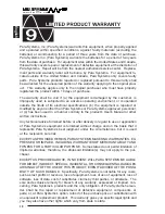
Page 19: ...en used in a manner contrary to the product s User s Manual or other written instructions Any technical advice furnished before or after delivery in regard to use or application of Para Systems s equi...

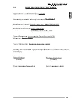
Page 20: ...nufacturer sAddress 1455 LeMay Drive Carrollton Texas 75007 USA Type of Equipment Uninterruptible Power Supplies UPS Model No EN400 EN600 I hereby declare that the equipment specified above conforms t...

Page 21: ...Para Systems Inc 1455 Lemay Dr Carrollton TX 75007 Phone 1 972 446 7363 Fax 1 972 446 9011...

Reviews: