4
OPERATING INSTRUCTIONS
1.
Filling: Fill the solution tank with the desired amount of water and add liquid cleaning solution
to the proper dilution ratio. DO NOT USE powdered cleaning chemicals. Powders are unlikely
to dissolve thoroughly, resulting in clogging the in-line solution filter. This can reduce or stop
water flow to the brush.
2. Close
lid.
3.
Turn on main power key switch (refer to page 5, #15).
4.
Adjust main speed control knob (#14) to full counter-clockwise position.
5.
Lower brush assembly:
•
Depress foot pedal (#6) slightly and push in on lever (#4) to release. To increase brush
pressure, pull up and back on lever (#4) to lock position.
•
To lift the brush, press the pedal down until lift mechanism engages.
•
Brushes will begin to rotate when forward (#16) or reverse (#8) levers are engaged.
6.
Adjust solution control feed lever (#3).
8.
Lower squeegee assembly with lever (#2). This will turn on the vacuum motor. The vacuum will
remain on until the squeegee lever (#2) is raised. After this, the motor will continue to run for
an additional 10 seconds to clear the recovery lines.
Turning off the power using the key switch will immediately shut down all systems,
including vacuum motor, transaxle, and solution feed.
9.
Squeeze forward handle (#16), and adjust forward speed using control knob (#14).
After
Use:
1.
Raise brushes with foot pedal (#6), brushes and solution flow will turn off .
2.
Raise squeegee assembly; vacuum will shut off 10 seconds after raising.
3.
Solution and recovery tanks should be emptied after every use. These tanks can be
emptied using drain hoses (#5 & #19).
MAINTENANCE
Daily:
1. Clean float assembly & squeegee blades.
2. Recharge batteries (check battery acid levels before and after charging).
Monthly:
1. Check wear on squeegee blades.
2. Grease front and rear wheels.
3. Grease pivot points on the brush motor assembly.
Every 500 hours check the condition of carbon brushes on vacuum motor and brush drive motor.
Summary of Contents for E320CE
Page 2: ......
Page 6: ...3 CONTROL PANEL IDENTIFICATION ...
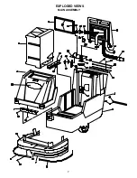
Page 10: ...EXPLODED VIEWS MAIN ASSEMBLY 7 ...
Page 12: ...SOLUTION AND RECOVERY TANK 9 ...
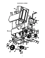
Page 14: ...MAINFRAME ASSEMBLY 11 ...
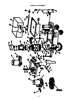
Page 16: ...LINKAGE ASSEMBLY 13 ...
Page 18: ...CONTROL PANELS 15 ...
Page 20: ...SQUEEGEE LIFT MECHANISM ASSEMBLY P N 260660 17 ...
Page 22: ...SQUEEGEE ADJUSTMENT MECHANISM ASSEMBLY P N 241730 1 19 ...
Page 23: ...SQUEEGEE BLADE ASSEMBLYP N 281579 20 ...
Page 24: ...21 ...
Page 25: ...22 ...
Page 26: ...23 ...
Page 27: ...24 ...


