background image

2. Introduction  


The RPM is an Internet ready device designed and equipped with an intelligent current-meter (True 
RMS) that will indicate the total power consumption of the RPM.  


Features: 


  Built-in Web Server to support Remote Power Management 

  Local LED displays Amps, IP Address ,Temperature or Humidity 

  Daily, Weekly, Monthly & Yearly Power Consumption Data 

  10/100 Base-T Ethernet Port 

  IPv4 and IPv6 support 

  SNMP support (v1,v2c,v3) 

  Telnet, SSHv2 Encryption support 

 Radius 

Authentication 

  User Account for three different permissions management systems 

  Alarm notification via Email, SNMP, Syslog, LED or audible alarm 

  SSL Web Browser (Https) for set up and operation 

  IP Address filtering 

  Maximum 5000 entries for each power consumption Data and Event log 

  Remote firmware upgrade support 

  SNMP Heart Beat Trap available 

  Reports in Fahrenheit or Celsius 

  Export and Import RPM configuration


  True RMS current measurement 

  Provides Voltage, Frequency, Power Factor, Active power, Apparent power and kWh information 

  Remote outlet On/Off power switching 

  Remote outlet current monitoring 

  User defined alarm thresholds for Warning and Overload 

  User defined power On/OFF sequence timing 

  Timed & Scheduled On/Off/Reboot switching 

  Alternative outlet restart mode: Memorize previous status, Always On or Always Off  

 Ping-No-Answer 

alarm 

  Outlet Action via Pre-set Event, Including Power Event, Environment Event and Receiving Trap 

from other devices 

  Circuit Breaker protection 

  Free bundle Management Utility 


Summary of Contents for 90001277

Page 1: ...RPM30241EV6 RPM30242EV6 Remote Power Manager User s Manual ...

Page 2: ...ble of Contents 1 IMPORTANT SAFETY INSTRUCTIONS 2 2 Introduction 4 3 RPM Package 5 4 Function 6 5 Installation 8 6 Web Interface 9 7 Specifications 29 8 Obtaining Service 30 9 Limited Product Warranty 31 ...

Page 3: ...e the RPM is exposed to direct sunlight Select a location which will provide good air circulation for the RPM at all times CAUTION To reduce the risk of fire connect only to a branch circuit with over current protection in accordance with the National Electric Code CAUTION Connect the RPM to a two pole three wire grounding AC wall outlet The receptacle must be connected to the appropriate branch p...

Page 4: ...ts for use in such applications unless it receives in writing assurances satisfactory to Para Systems that a the risks of injury or damage have been minimized b the customer assumes all such risks and c the liability of Para Systems Inc is adequately protected under the circumstances COPYRIGHT 2015 BY PARA SYSTEMS INC All Rights Reserved All rights of this User Manual Manual including but not limi...

Page 5: ...t up and operation IP Address filtering Maximum 5000 entries for each power consumption Data and Event log Remote firmware upgrade support SNMP Heart Beat Trap available Reports in Fahrenheit or Celsius Export and Import RPM configuration True RMS current measurement Provides Voltage Frequency Power Factor Active power Apparent power and kWh information Remote outlet On Off power switching Remote ...

Page 6: ...r Manager unit with supporting hardware The contents of the package are Remote Power Manager Unit The rackmount brackets are installed on the RPM CD ROM which contains User Manual RPM Utility Manual Warranty Card MIB files RPM Utility Software Adobe Acrobat Reader ...

Page 7: ...idity ID 1 digit will display the identification number of the RPM Function Button Press and release the function button to turn off the audible alarm Note The overload alarm cannot be silenced Press and hold the function button for 1 beep then release will display the ID number the temperature and the humidity for both of the Temperature Humidity Probes Press and hold the function button for 2 be...

Page 8: ...er 1 second Overload 3 beeps per 1 second Note The audible alarm will continue to beep until the current is lower than the threshold by 0 5 amps Ethernet The RJ45 port is for the network communication Outlets A X Each individual outlet can be controlled and monitored Power Cord Connect to utility power ...

Page 9: ...ore of wire between the electrical outlet and the electrical service panel The RPM comes with the mounting brackets pre installed To mount the RPM into a rack perform the following procedure 1 Select the desired location for the RPM 2 Align the mounting holes of brackets with the notched hole on the vertical rail and attach with the retaining screws 3 Connect the Ethernet cable to the RPM 4 Connec...

Page 10: ...PM in a web browser Note The default setting for the IP address is DHCP enabled If the RPM cannot get the IP from the DHCP server the IP address will remain at the default IP address 192 168 0 216 The default user Name is snmp The default Password is 1234 ...

Page 11: ...odel you have may not display the same information Outlet Status Setting Column S The schedule function is set The RPM will execute the preset action according to the schedule P The ping function is active If the specified device stops responding to the ping the RPM will execute the preset action according to the ping function E The RPM will execute the preset action when the event occurs accordin...

Page 12: ...ormation Power This section shows the information about the power the current draw and status for each individual outlet Information System This section shows the information about the System Network and SNMP ...

Page 13: ...ased on specific dates and times The event logs can be downloaded and saved for future reference Information Data Log This table lists all of the saved power and environmental data The existing values are over written when the maximum number of entries 5000 has been reached You can filter the log based on specific dates and times The event logs can be downloaded and saved for future reference ...

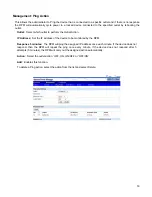
Page 14: ... group Rename Rename a group Note After the RPM is plugged into the main power the RPM will automatically start to sequentially turn on the outlets according to the preset delay time The default setting for delay time is one second for each outlet therefore the three circuits with 8 outlets each will take 8 seconds to complete the start up sequence If the RPM is unplugged from the main power befor...

Page 15: ...he administrator to assign the outlets to make a group Click on the Group button Name the group 36 characters max select the outlets to include in the group and click Add Select the check box by the group that you want to control ...

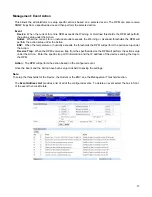
Page 16: ...e outlet to be controlled in this schedule Outlet Action Select the action you want to occur Date When selecting the Once option a specific date must be entered When selecting the Every option you can set the schedule for an outlet using an assigned weekly day or every day Time Set the time for the action to occur ...

Page 17: ...Action IP Address Set the IP address of the device to be monitored by the RPM Response 5 minutes The RPM will ping the assigned IP address once each minute If the device does not respond then the RPM will repeat the ping once every minute if the device does not respond after 5 attempts 5 minutes the RPM will carry out the assigned action automatically Action Select the outlet action OFF ON ON OFF ...

Page 18: ...ature or humidity exceeds the thresholds the RPM will perform the action setup under the Action Receive Trap When the RPM receives a trap from the specified device the RPM will perform the action setup under the Action Enter the specific trap OID information and the IP address of the device sending the trap to the RPM Action The RPM will perform the action based on the configured event Once the Ev...

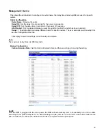
Page 19: ...setup different users for specific outlets The user accounts must be setup first see the Configuration User tab Click Apply to save the settings once the setup is complete Note The maximum delay times are 9999 seconds Energy Configuration Carbon Emission Rate Set the Carbon Emission Rate and then select Apply to saving the setting Note After the RPM is plugged into the main power the RPM will auto...

Page 20: ...pper thresholds for the optional environmental probe then click Modify to change the settings Once these thresholds are set see the management Event Actions to configure the actions based on these thresholds Device Threshold Configuration Set the warning and overload thresholds for entire RPM then click Modify to change the settings Once these thresholds are set see the management Event Actions to...

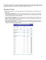
Page 21: ...k for your network Gateway IP The IP address of the IVP4 network gateway DNS Server1 The IP address of the primary DNS server DNS Server1 The IP address of the secondary DNS server Once the information has been entered click Apply to save the settings TCP IP Settings for IPv6 DHCP Client Enable Disable DHCP to get the IP address from DHCP server The default setting for the IPv6 DHCP is disabled IP...

Page 22: ...Port Number The user may configure port number for the HTTP port default 80 or the port number for the HTTPS port default 443 Once the information has been entered click Apply to save the settings Telnet Configuration Server Enabling or disabling the Telnet connection with the RPM SSH Enabling or disabling the SSH connection with the RPM Port Number The user may configure Telnet protocol to use a ...

Page 23: ...r user Monitor the RPM control the specified outlets No permission to configure RPM Default password is password View Only Monitor the RPM only No permission to control or configure the RPM Default password is password Email Enter an email address for the recipient you want to receive the notification To add a new user 1 Enter the user name and then click New 2 Enter the password 3 Confirm the pas...

Page 24: ...ck this box if using secure email Email Server Requires Authorization Check this box if the Mail Server requires authentication to send emails Account Name Enter the account name if SMTP authentication is required Password Enter the password if SMTP authentication is required Test Input the recipient s email address Click on the Send button to send the test email Click Apply to save all of the set...

Page 25: ... traps to satisfy most of the user s environment This allows the administrator to setup the SNMP Traps When an event occurs the RPM can send out SNMP Traps to predefined targets Once the SNMP configuration is complete click the Apply button to save the settings ...

Page 26: ...to setup the system time for the scheduled events Time Configuration Set the date and time manually and then click the Apply button to save the settings SNTP Configuration Activate and then setup the Timeserver Click the Apply button to save the settings ...

Page 27: ...address Shared Secret Input the Shared Secret of Primary Server Port Input the RADIUS UDP port for the primary server Timeout Set the packet timeout interval Retries Set the number of retries before locking out the user Secondary Server Input the Secondary RADIUS Server s IP address Shared Secret Input the Shared Secret of Secondary Server Port Input the RADIUS UDP port for the secondary server Ti...

Page 28: ...mat Syslog Configuration Configure the RPM1581EV6 to send Systems logs Data Log Configuration Set the time interval to record the data logs Heartbeat Interval Enable or Disable the Heartbeat Trap and set the interval time Event Log Configuration Check the events you want to receive notifications for via emails SNMP traps or SMS messages ...

Page 29: ...her RPM Firmware Upgrade The firmware can be upgraded via the web page Reset System Reset the system back to the factory default setting Hardware Reset Button Definition Configure how the reset button functions Temperature Scale Configure how the temperature for the external Temp Humidity probe will be displayed Auto Logout Configure the amount of time before the system will log you off ...

Page 30: ...149 F 0 65 C Operating Storage Humidity 0 90 non condensing Operating Elevation 0 to 3 000m 0 to 10 000 ft Storage Elevation 0 to 15 000m 0 to 50 000 ft PHYSICAL Input Power Cord 10 feet attached Input Plug NEMA L5 30P NEMA L6 30P Quantity Output Receptacles 24 Type Output Receptacles NEMA 5 15 20R IEC 320 3 C19 21 C13 Rack Mounting Format Vertical Zero U Net Dimension L x W x H mm 70 x 2 2 x 3 15...

Page 31: ...nician will ask you for the above information and if possible help solve the issue over the phone In the event that the unit requires factory service the technician will issue you a Return Material Authorization Number RMA NOTE We must have the model number and the serial number of the product to issue the RMA h If the unit is under warranty the repairs will be done at no charge If the unit is not...

Page 32: ...een used in a manner contrary to the product s User s Manual or other written instructions Any technical advice furnished before or after delivery in regard to use or application of Para Systems equipment is furnished without charge and on the basis that it represents Para Systems best judgment under the circumstances but it is used at the recipient s sole risk EXCEPT AS PROVIDED HEREIN PARA SYSTE...

Reviews: