background image

9

CONNECTING THE  HARDWARE

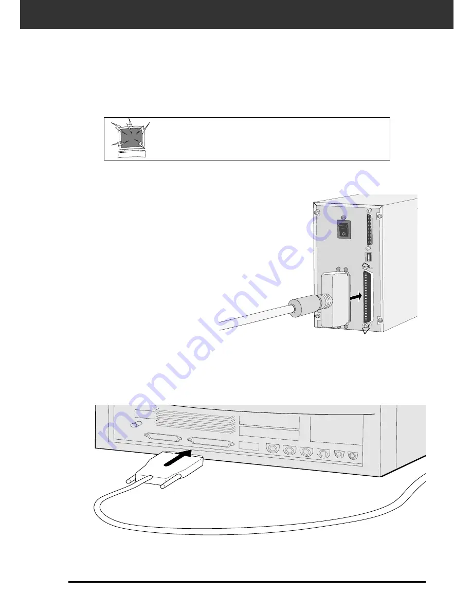
2. Connect one end of the SCSI cable to either SCSI

port on the back of the scanner

• Either SCSI port can be used for other configurations, there is no

dedicated in or out port.

1. Place the scanner on a level surface.

3. Connect the other end of the SCSI cable to the

SCSI port on the computer or the last device in
the SCSI chain.

Continued on the following page.

Connecting the SCSI Cable

This scanner has been packaged with the SCSI cable SC-11 (DB25-to-SCSI-1). See your dealer if
you require a different SCSI cable.

• To meet FCC regulations, the SCSI cables used with this scanner must be equipped with ferrite cores.

BEFORE YOU  BEGIN…
TURN THE COMPUTER AND ALL CONNECTED
DEVICES OFF.

Summary of Contents for DIMAGE SCAN ELITE

Page 1: ...9224 2885 11 H A909 E INSTRUCTION MANUAL...

Page 2: ...classe B est comforme la norm NMB 003 du Canada Changes or modifications not approved by the party responsible for compliance could void the user s authority to operate the equipment This manual may n...

Page 3: ...on the power cord Do not connect the ground to a gas pipe telephone ground or a water pipe Improper grounding can result in electric shock This product must have sufficient ventilation while in use B...

Page 4: ...roved for use on NEC PC 9821 series machines Do not use AVA 1505AE AHA 1520B and AHA 1540CP SCSI boards with NEC PC98NX Series machines Support will not be provided for malfunctions or problems caused...

Page 5: ...of available hard disk space Mac OS 7 5 to 8 6 Standard SCSI board SCSI expeansion card inserted in PCI NuBus must not be used New Power Macintosh G3 series Blue and White use Adaptec PowerDomain 2940...

Page 6: ...ould be included in this package Software Registration Please register this software before using it Once registered you will receive technical support software upgrade and product information Complet...

Page 7: ...e Correction Tone Curves Histogram 35 Image Correction Brightness Contrast Color Balance 40 Image Correction Hue Saturation Lightness 42 Image Correction Variation Correction 44 Image Correction Snaps...

Page 8: ...6 SCANNER NAMES OF PARTS 1 Indicator lamp 2 Film slot 3 Film door 4 Power switch 5 SCSI port DB25 6 Terminator power switch 7 SCSI ID switches 8 SCSI port SCSI 1 9 AC socket...

Page 9: ...SCANNER SETUP...

Page 10: ...uter and all connected SCSI devices SCSI ID Dip Switch Settings 3 Using a pointed object set the switches to an unused SCSI ID The Dim ge Scan Elite s SCSI ID is factory preset to 5 If 5 is not occupi...

Page 11: ...the other end of the SCSI cable to the SCSI port on the computer or the last device in the SCSI chain Continued on the following page Connecting the SCSI Cable This scanner has been packaged with the...

Page 12: ...o the open port on the back of the scanner If there are other devices in your SCSI chain 5 Plug the power cord into the scanner s AC socket then plug it into a grounded outlet This decive is to be use...

Page 13: ...Plug the power cord into the scanner s AC socket then plug it into a grounded outlet 4 Turn the terminator power switch switch 4 to ON An external terminator is not necessary with this scanner If the...

Page 14: ...is dialog box may appear several times Repeat step 3 until the dialog box no longer appears Windows NT 3 Select Start Settings Control Panel then double click on the SCSI Adapters icon Confirm that Mi...

Page 15: ...d the software will not be installed 6 Select D DRIVER ENGLISH Setup exe from the Open drop down list then click on OK If your CD ROM drive is not the D drive replace the D with the appropriate design...

Page 16: ...INSTALLING THE SOFTWARE PC AT 14 10 Choose either Typical or TWAIN Files install then click on Next The Setup Type dialog box will appear The Select Program Folder dialog box will appear The Setup Suc...

Page 17: ...the software will not be installed The End User License Agreement will appear The installer s start up screen will appear 6 Open the English language folder then double click on the Dim ge Scan Elite...

Page 18: ...drive or folder and type from the pulldown menus You can also click on to select an install drive The following dialog box will appear Install type pulldown menu Install location pulldown menu Name an...

Page 19: ...I O N S C A N F L O W Set the Preferences Launch the Software Load the Film Holder Insert the Film Holder Specify the Film Type Prescan Specify the Job Type Orient the Image Correct the Brightness Co...

Page 20: ...Driver Windows This manual uses Adobe Photoshop 4 0 1 as the host application Commands may vary among applications 1 Open the host application 2 Select File Import Select TWAIN_32 Source 3 Select DS_E...

Page 21: ...hotoshop 3 0 5 Select File Acquire DS_Elite Plug in The software is ready for use when the Main window appears p 20 Launching the Utility Software Select Start Programs Minolta Dim ge Scan Elite DS El...

Page 22: ...format list box Index Scan button Prescan button Scan button Navigation button Close button Status bar Help button on Macintosh Preferences button APS Rewind button Index scan see page 56 Prescan see...

Page 23: ...channel used to scan your image RGB or CMY Three options are available 8 bit over 16 7 million colors 16 bit over 2 8 billion colors 16 bit linear same as 16 bit but image correction is not applied w...

Page 24: ...ta Dim ge Scan Elite can scan mounted or unmounted 35mm colour negatives 35mm colour slides 35mm black white negatives 35mm black white positives Advanced Photo System negatives and slides can also be...

Page 25: ...ight from the line scanner producing bad results 1 Insert slides into the slide holder emulsion side up Brush dust off the the slide before placing it into the film holder Slide mounts must be thicker...

Page 26: ...e of the film holder Remove flip then re insert the film holder to scan the frames on the other side of the holder Remove flip then re insert the negative holder to scan frames 4 5 or 6 Frames 3 or 4...

Page 27: ...e Preview window appears 2 Select the film type from the film type drop down list 3 Click on in the Main window The previewed image will appear in the Preview window Press Ctrl when previewing on the...

Page 28: ...clicking on the Scan button This ensures that the final scan will be the best it can be Rotate Left buttonZoom button Frame number indicator Auto Holder Mount Crop Adjustment button AE Lock button AE...

Page 29: ...re settings AE lock does not save exposure corrections made in the Variations or Tone Curves Histogram dialog boxes 1 Click on can not be selected until an image has been previewed After previewing th...

Page 30: ...the image 2 Press the Shift key The AE area is indicated by a line instead of the cropping area which is indicated by a dashed line 3 While pressing down the Shift key change the AE area The operation...

Page 31: ...ick on the and buttons to correct the orientation of your image before scanning Changes will be reflected in the preview image Rotate Click on to rotate the image 90 clockwise Click on to rotate the i...

Page 32: ...ht or top to bottom before scanning Changes will be reflected in the preview image Flip Click on to flip the image left to right Click on to flip the image top to bottom The image is upside down compa...

Page 33: ...ation The cropping frame defines how much of the preview image will be scanned The dimensions of the cropping frame are displayed in the lower left corner of the preview window Cropping To enlarge or...

Page 34: ...cing the View 1 Click on in the Preview window The pointer will change to 1 Press and hold the Ctrl key option key on the Macintosh to reduce the image magnification The pointer will change to 2 Click...

Page 35: ...to display the APS cropping frames The cropping frames are displayed in sequence with each click of the CHP button This function allows you to display the current frame number and the total number of...

Page 36: ...ain window Undo button Correction Reset button Snapshot button RGB CMY display Image Correction Job Save button Image Correction Job Load button Pre Post Correction Comparison Display button Full Scre...

Page 37: ...olor The level is indicated in 256 color steps 0 to 255 from the left to right The tone curves and histogram are linked to each other so that when the tone curve is corrected the histogram is automati...

Page 38: ...he portion of the curve to be changed The coordinate value of the cursor is displayed from 0 to 255 The corrected image by changing the tone curves is applied to the preview image You can also change...

Page 39: ...m of Each R G B color 1 Click the RGB Display button When the RGB Display button is clicked again the histogram of each R G B channel disappears The input slide bar has the Input shadow slider Input g...

Page 40: ...his function allows you to correct the highlight or shadow point to the specified value Changes are automatically applied to the preview image 1 Double click the White Point button The Point Value dia...

Page 41: ...g the Histogram of Images After Making Corrections When the Apply button is clicked the histogram of images after making corrections can be displayed The histogram after making corrections is displaye...

Page 42: ...mages can be corrected by dragging the slider or inputting the desired value in the text box Click on in the Image Correction window Post Correction LUT Contrast text box Color Balance text box Post C...

Page 43: ...st Correction LUT The color of the image is changed as shown in the Post Correction LUT The correspondence between the color displayed on the Pre Correction Gray Scale and Post Correction Gray Scale a...

Page 44: ...lour move the Hue Saturation or Lightness slider or input the desired value in the text box Moving the slider changes Pre Correction Color Sample and Post Correction Color Sample Pre Correction Color...

Page 45: ...on is clicked the saturation of the image is corrected automatically without changing the hue and lightness IMAGE CORRECTION HUE SATURATION LIGHTNESS Reset If you click the Reset button the settings i...

Page 46: ...ection items are displayed 2 Click the correction item The variation frames are corrected according to the selected correction item IMAGE CORRECTION VARIATION CORRECTION The Variations Dialog Box Name...

Page 47: ...e image by repeating the operation in step 2 The 8 images of which brightness and contrast have been corrected by one step in horizontal and vertical direction respectively for the center image are di...

Page 48: ...t to correct from the 2 frames of the images except for the image in center The image you clicked is placed in the centre and 2 new frames of the variation images that have been corrected are displaye...

Page 49: ...nt corrections to be made and then compared without having to go back and retrace previous correction steps Storing in the Snapshot Display Area temporarily 1 Click on The displayed preview image is d...

Page 50: ...is clicked the size of the pre and post correction image is automatically changed according to the size of the main window Checking the Correction Result While Lining Up Images When the Pre Post Corr...

Page 51: ...ting is saved as an image correction job The image correction setting in each correction window can be saved as an image correction job You can easily correct the image by loading the apporopriate cor...

Page 52: ...elect the image correction job and click on the OK button Image Correction job display area Original image display Canceling the Image Correction When the Undo button is clicked the current image corr...

Page 53: ...he Navigation button is clicked in the Main window the navigation window is displayed The Navigation Dialog box Name of parts Operation Item checkbox Navigation Flow APS Repeated Operation Item checkb...

Page 54: ...operation When using a film format other than APS the index scan film frame selection and rewind cannot be selected 1 Insert the check mark in the operation items to be performed as the automatic ope...

Page 55: ...ting The Navigation set saving dialog box is displayed 3 Input the setting name and click the OK button Selecting a Navigation setting 1 Click on the arrow next to the Navigation menu list to display...

Page 56: ...mage displayed in the Preview window 1 Click on in the Main window 2 Enter the desired file name and select the file destination 3 Select the file type from the drop down list 4 Click on The final sca...

Page 57: ...tware Load and Insert the Film Holder Specify the Film Type Prescan Scan Save Index Scan Select Frame s to Prescan from Index Print OR Select Frame s to Prescan Orient and Crop Correct the Contrast Br...

Page 58: ...6 LAUNCH SOFTWARE SPECIFY FILM TYPE 1 Launch the software pp 18 19 2 Select APS Cassette from the film format drop down list in the main window 3 Select the film type from the film type drop down list...

Page 59: ...mage Auto Film Rewind Clicking on the eject button in the Command window automatically rewinds the film into the APS cassette before the APS adapter is ejected Rotate All Frames 180 Rotates all frames...

Page 60: ...he APS Adapter 1 Slide the film chamber release as shown The film chamber door will open 2 Insert the film cassette into the film chamber with the VEI Visual Exposure Indicator on top 3 Close the film...

Page 61: ...APS ADAPTER OPTIONAL 59 then open the scanner s film door 1 Press the door where shown to unlock 2 Insert the APS Adapter into the scanner Inserting the APS Adapter...

Page 62: ...lick on the appropriate image box in the index window to select an image for prescanning or scanning There are two options for making an index scan Speed or Quality Select the desired option in the Pr...

Page 63: ...l the index scan press the escape key Command and period for the Macintosh until the Cancelling Index Scan message box appears The completed index scans will appear in the index window Frames that hav...

Page 64: ...s not change When the Full Screen View button is clicked the size of the index frames changes automatically and all frames are displayed Select the desired frames then click on or The selected frames...

Page 65: ...w Adjustments made in the Preview window are held until the image is scanned or the driver software is closed 3 Apply contrast brightness and colour corrections pp 34 46 2 Orient and crop the image as...

Page 66: ...lications can only acquire one image at a time Press the shift key while clicking to select all the frames between the current frame and the last frame selected Press the control key key for the Macin...

Page 67: ...an Elite driver software The driver window will close automatically after each scan if the Close Application After Scanning option was selected in the Preferences dialog box p 21 2 Remove the APS adap...

Page 68: ...66...

Page 69: ...A P P E N D I X...

Page 70: ...ronments in addition to the color space setting specify the monitor ICC profile settings in both the driver software and a software such as Photoshop For details refer to page 69 1 Click on in the Mai...

Page 71: ...ile 1 select for Windows This is not used for Macintosh When using an application of which the monitor colour matching function is set to ON Output colour space 2 option ICC profile 1 select When usin...

Page 72: ...indow Index window or Preview window The Scan Settings part in the Main Window Names of parts Except the Image Correction window in the Main window Job Name list box Output Size text box H Units list...

Page 73: ...r software automatically determines the input resolution necessary to obtain the desired output size and resolution 2 Select the appropriate category from the drop down list 1 Click on in the Index wi...

Page 74: ...ximum 3 digits The output size is limited by the maximum resolution of the scanner The values will change if a different unit of measure is selected The output size cannot be changed when the unit lis...

Page 75: ...ngs in the Main window Index window or Preview window 2 Click on 3 Name the job by entering a title and select the desired category then click on It is possible to delete the Job you created when it i...

Page 76: ...i 360 dpi 267 dpi and 180 dpi There are ten paper size options Dye Sub Printer Dye sublimation printers Uses an output resolution of 300 dpi There are 4 paper size options Ink Jet Printer Uses an outp...

Page 77: ...116 00 ON 14x17_180dpi 2123 180 1179 mm 36 3 24 2 OFF 428 00 285 00 ON 11x14_180dpi 1747 180 970 mm 36 3 24 2 OFF 352 00 235 00 ON 10x12_180dpi 1494 180 830 mm 36 3 24 2 OFF 301 00 200 00 ON unavailab...

Page 78: ...xel 1280 853 OFF 1280 853 ON 1152 x 870 805 300 268 pixel 1152 768 OFF 1152 768 ON 1024 x 768 716 300 238 pixel 1024 682 OFF 1024 682 ON 832 x 624 582 300 194 pixel 832 554 OFF 832 554 ON 800 x 600 55...

Page 79: ...2776 300 925 inch 1 18 0 68 OFF 10 90 6 30 ON Letter Half 2161 300 720 inch 1 18 0 68 OFF 8 50 4 90 ON Letter Quarter 1385 300 461 inch 1 18 0 68 OFF 5 45 3 14 ON Letter Eighth 1080 300 360 inch 1 18...

Page 80: ...e contrast of only the middle tones HIGHLIGHTS The lighter areas of the image HISTOGRAM A graph showing the amount of each level of the 256 brightness levels INTERPOLATION A form of adding new pixels...

Page 81: ...many pixels in a given area RGB Red Green and Blue These are the colours of the three channels that make up the scanned image Monitors use red green and blue phosphors to create the image you see on t...

Page 82: ...then restart your system Check that the SCSI ID is not being used by another SCSI device Setting up now Remove the film holder Remove the film holder and click on OK Set film properly Indicator lamp...

Page 83: ...SI Ports DB25 Centronics 50 Light Source 3 Wavelength Cold Cathode Fluorescent Power Frequency Product for North America 100 120 volts AC 50 60 Hz Product for Europe 220 240 volts AC 50 60 Hz This dev...

Page 84: ...e following information ready when calling Minolta Technical Support Determining the version number of your driver software Place the pointer on the status window in the command window to display the...

Page 85: ...83 NOTES...

Reviews: