Minolta Bizhub 36 Installation Manual Download Page 8

E-8

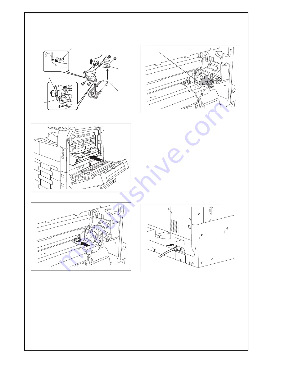
17. Screw the drum unit in position. (Two silver 

screws each on the right and left sides)

Note:

Use care not to touch or scratch the photo conduc-
tor.

18. Install the imaging unit (IU) in position.

19. Connect the connector.

20. Install the cover shown in the illustration. 

(One screw)

Note:

Make sure that the hole of the cover is aligned with 
the positioning pin of the machine.

Note:

    • After setting the IU in place, do not close the 

right door.

    • After setting the IU in place, promptly plug the 

power cord into an outlet and clear the counters 
within one minute. 
(See the next section for information on clear-
ing the counters.)

XIII. Connecting the power cord

1. Connect the power cord.

Note:

This step may not be performed depending on the 
applicable marketing area.

A3EW11A018AA

Positioning pin

Shaft

Guide

Guide

Shaft

A3EW11A015CA

A1UDIXC014DA

Positioning pin

A1UDIXC007DB

Hole

A1UDIXE035DA

Summary of Contents for Bizhub 36

Page 1: ...s must be installed after completing the main body instal lation When placing the machine on the floor make sure to use the paper feed cabinet or the desk to secure the performance and the quality of the product Once the Power Switch is turned ON do not turn OFF it until the installation work has been completed Lifting the machine in an awkward position or transporting it in a poorly balanced posi...

Page 2: ...y parts Varies depending on the applicable marketing area Note This manual provides the illustrations of the acces sory parts and machine that may be slightly differ ent in shape from yours In that case instead of the illustrations use the appearance of your machine to follow the installation procedure This does not cause any significant change or problem with the procedure 1173 46 3 16 1187 46 3 ...

Page 3: ...ne mass Approx 63 kg 139 lb Make available collective manpower of an appropriate size for transporting the machine When attaching the machine as the reference fit the machine with the corner A and B of the paper feed cabinet VI Removing protective tape packing and other shipping materials 1 Remove the protective tapes and the protective materials A B A1V4IXC010DA A3EW11A003BA A3EW11A004AA A3EW11A0...

Page 4: ...ed spacer onto the back of the main body Note This step may not be performed depending on the applicable marketing area VIII Installing the user s guide holder Install the user s guide holder IX Affixing the paper size label Affix the paper size label For loading the paper as well as setting the paper type refer to the user s guide Affix the paper size labels under the labels that show the number ...

Page 5: ...Loading the developer 1 Open the right door 2 Remove the cover shown in the illustration One screw Note After removing the screw 1 Raise the cover slightly 2 Pull it out toward you Do not touch scratch or otherwise damage the photo conductor 3 Disconnect the connector Note Do not touch scratch or otherwise damage the photo conductor When pulling out the connector use caution not to break the cable...

Page 6: ... while slightly bend ing open its lower part the shaded portion Note Do not touch or scratch the photo conductor Cover the drum unit which has been removed with a protective cloth or similar tool 7 Remove the developing unit cover Three screws 8 Remove the toner supply port 9 Remove the supplied sheets of mylar from the paper backing A3EW11A015BA A3EW11A017AA Drum unit Developing unit Drum unit De...

Page 7: ...the col lar 12 Remove the mylar sheets that were attached in step 10 Two places Note Discard the removed mylar sheets 13 Reinstall the toner supply port Note Make sure of the correct mounting position and direction 14 Reinstall the developing unit cover ensuring that its tabs are fitted properly into the slits Three screws 15 Align the shaft of the developing unit with the inner guide of the drum ...

Page 8: ...he positioning pin of the machine Note After setting the IU in place do not close the right door After setting the IU in place promptly plug the power cord into an outlet and clear the counters within one minute See the next section for information on clear ing the counters XIII Connecting the power cord 1 Connect the power cord Note This step may not be performed depending on the applicable marke...

Page 9: ...t o TCR Sensor Adjustment 4 Touch Execute o OK Note After touching OK wait about 1 minute 30 sec onds as is 5 Touch Close 6 Touch Close on the Service Mode screen XVI Installing the toner bottle Note The toner bottle is not shipped with the machine Purchase one that is separately available 1 From a height of about 10 cm tap the toner bottle against a table or other hard object four to five times T...

Page 10: ...r back into the machine until it clicks into position Then close the front door XVII Adjusting touch panel 1 Press the Utility Counter key 2 Touch Accessibility o Touch Panel Adjust ment 3 Lightly touch the center of the markers at four places on the touch panel Touch in any order Note Pressing the touch panel hard may cause dam age When all the markers at four places have been touched the Start k...

Page 11: ... scanning of the test patterns is com plete return to the Gradation Adjustment screen 7 Touch Gradation Adjustment o Print o OK Test pattern will then be produced on the A4 or Letter size paper 8 Touch Scan Using the steps below follow the panel display to start scanning the test patterns 1 Place the test pattern Gradation adjustment sheet face down on the document glass and close the original cov...

Page 12: ...ers 2 Make sure that the Service Mode screen is dis played 3 Touch Printer Adjustment Leading Edge Adjustment 1 Touch Side Edge Adjustment o Tray 4 2 Press the Start key A test print will be produced 3 Measure widths B and C of the pattern on the test printout and check that the difference is within the specified range Specifications Width B Width C 0 1 0 mm 4 If the difference between the measure...

Page 13: ... the or key Adjustable range 3 0 to 3 0 mm Step 0 2 mm 5 Print a test page again and check if the differ ence is within the specified range Adjust Tray 5 using the same steps 6 Touch Close twice 7 Touch Close on the Service Mode screen 8 Turn ON OFF the Power Switch Note If Service Mode was displayed you must turn off the power after exiting Service Mode and turn it back on after 10 or more second...

Page 14: ...ss the Utility Counter key 2 Touch Admin Settings o Enter Admin pass word o Touch OK 3 Touch Ethernet o TCP IP o DHCP o OFF o OK 4 Set the following settings 1 Touch Enable o ON o OK 2 Touch IP Address o Set it to an IP address on the network of the machine o Touch OK 3 Touch Subnet Mask o Set the subnet mask o Touch OK 4 Touch Gateway o Set the gateway address o Touch OK 5 Turn OFF the Power Swit...

Reviews: