background image

26 (2720)A

REPAIR GUIDE

BB-60

BB-60

BB-60

BB-60

BB-60

BB-60

BB-60

BB-60

BB-60

BB-60

BB-60

BB-60

BB-60

BB-60

BB-60

9384-2190-50 (4)

9384-2190-50 (4)

9384-2190-50 (4)

9384-2190-50 (4)

9384-2190-50 (4)

( 4 x 1 4 m m )

( 4 x 1 4 m m )

( 4 x 1 4 m m )

( 4 x 1 4 m m )

( 4 x 1 4 m m )

AA-20

AA-20

AA-20

AA-20

AA-20

GG-115

GG-115

GG-115

GG-115

GG-115

GG-55

GG-55

GG-55

GG-55

GG-55

3256-2259

3256-2259

3256-2259

3256-2259

3256-2259

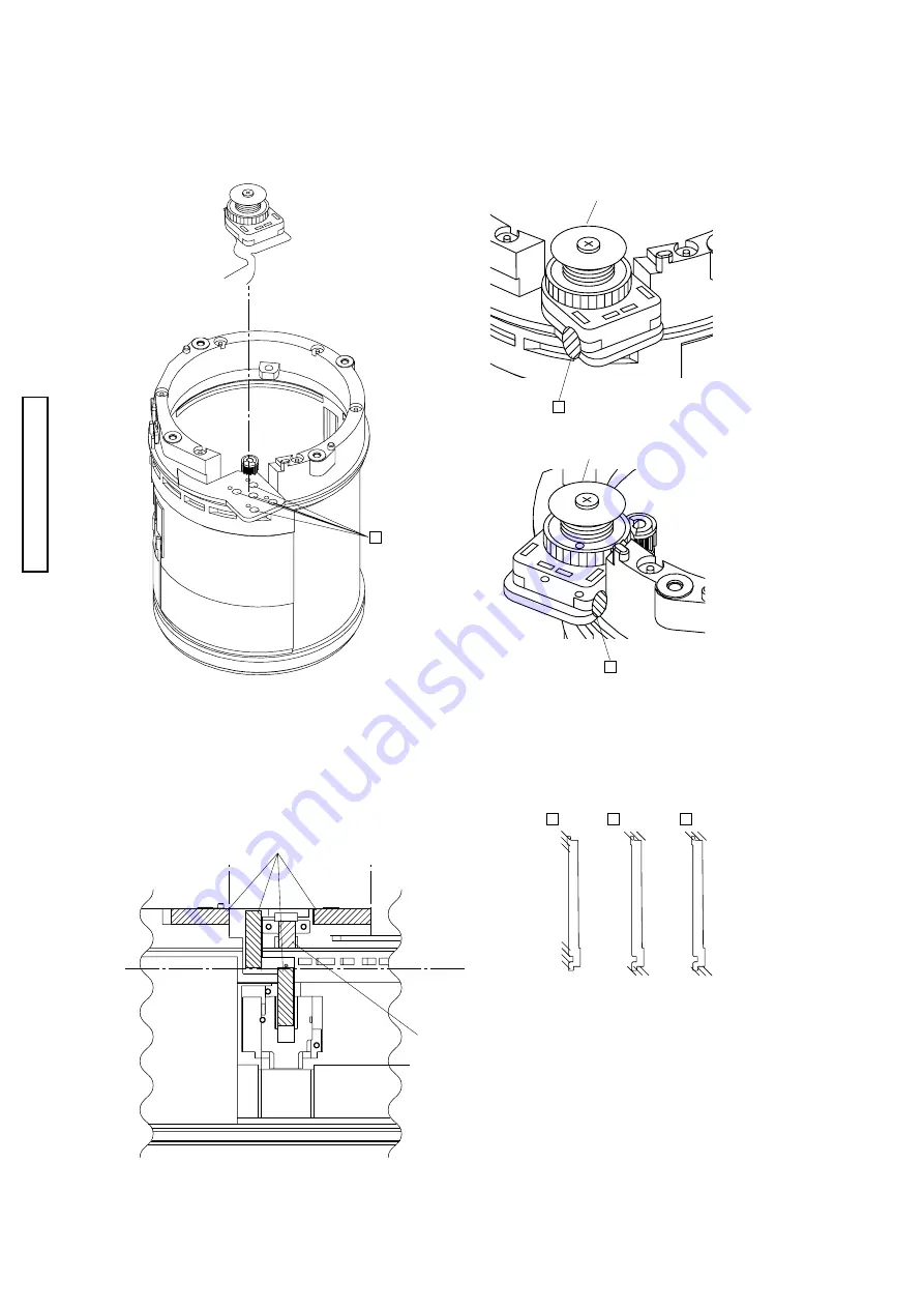
Fig.1 Sticking the zoom encoder FPC assy

Fig.1 Sticking the zoom encoder FPC assy

Fig.1 Sticking the zoom encoder FPC assy

Fig.1 Sticking the zoom encoder FPC assy

Fig.1 Sticking the zoom encoder FPC assy


    Apply B-60 to the directed parts of the outer barrel assy and the zoom encoder FPC assy.

Apply B-60 to the directed parts of the outer barrel assy and the zoom encoder FPC assy.

Apply B-60 to the directed parts of the outer barrel assy and the zoom encoder FPC assy.

Apply B-60 to the directed parts of the outer barrel assy and the zoom encoder FPC assy.

Apply B-60 to the directed parts of the outer barrel assy and the zoom encoder FPC assy.

Zoom encoder FPC assy

Zoom encoder FPC assy

Zoom encoder FPC assy

Zoom encoder FPC assy

Zoom encoder FPC assy

Zoom encoder FPC assy

Zoom encoder FPC assy

Zoom encoder FPC assy

Zoom encoder FPC assy

Zoom encoder FPC assy

Outer barrel assy

Outer barrel assy

Outer barrel assy

Outer barrel assy

Outer barrel assy

Zoom encoder FPC assy

Zoom encoder FPC assy

Zoom encoder FPC assy

Zoom encoder FPC assy

Zoom encoder FPC assy

Outer barrel assy

Outer barrel assy

Outer barrel assy

Outer barrel assy

Outer barrel assy

Outer barrel assy

Outer barrel assy

Outer barrel assy

Outer barrel assy

Outer barrel assy

Fig.2 Sticking 3256-2259 and 9384-2190-50

Fig.2 Sticking 3256-2259 and 9384-2190-50

Fig.2 Sticking 3256-2259 and 9384-2190-50

Fig.2 Sticking 3256-2259 and 9384-2190-50

Fig.2 Sticking 3256-2259 and 9384-2190-50


    Stick 3256-2259 and 9384-2190-50 onto the directed

Stick 3256-2259 and 9384-2190-50 onto the directed

Stick 3256-2259 and 9384-2190-50 onto the directed

Stick 3256-2259 and 9384-2190-50 onto the directed

Stick 3256-2259 and 9384-2190-50 onto the directed

part of the outer barrel assy.

part of the outer barrel assy.

part of the outer barrel assy.

part of the outer barrel assy.

part of the outer barrel assy.

Basic direction

Basic direction

Basic direction

Basic direction

Basic direction

for sticking

for sticking

for sticking

for sticking

for sticking

Basic direction

Basic direction

Basic direction

Basic direction

Basic direction

for sticking

for sticking

for sticking

for sticking

for sticking

Basic direction

Basic direction

Basic direction

Basic direction

Basic direction

for sticking

for sticking

for sticking

for sticking

for sticking

Outer barrel assy

Outer barrel assy

Outer barrel assy

Outer barrel assy

Outer barrel assy

Fig. 3

Fig. 3

Fig. 3

Fig. 3

Fig. 3


    Apply it to the shaded area of 2206.

Apply it to the shaded area of 2206.

Apply it to the shaded area of 2206.

Apply it to the shaded area of 2206.

Apply it to the shaded area of 2206.

Summary of Contents for A2

Page 1: ...exchanging parts 30 Relatedadjustmentandrequiredsettingitems 31 Preparing the 2782 adjustment program 32 Starting up the 2782 adjustment program in the adjustment mode 33 Contents of the adjustment program and CPU versionreadout 34 Setting the camera and the chart when adjustingtheCCDperspective 35 AdjustmentofCCDperspective 37 Sensitivityadjustment GAIN 39 Adjusting the center part of CCD CCDCENT...

Page 2: ...or cloth Never use thinner ketone ether 2 When installing plastic parts insert the specific screws vertically to the parts Be careful not to tighten too much PCBs Since PCBs use MOS IC you must reduce static electricity When repairing a PCB itself or when wiring please perform your work as illustrated below If grounding is impossible connect a cable to a steel desk or shelf Keep touching the condu...

Page 3: ...1 Fig 1 Fig 1 Fig 1 Fig 1 Discharge Before disassembly be sure to discharge the main condenser in the following manner Fig 1 Short circuit with discharger or resistor of 200 300 ohm 3w Check voltage to make sure it is discharged ...

Page 4: ... 5 Fig 3 5 Fig 2 Fig 2 Fig 2 Fig 2 Fig 2 Fig 1 4 Fig 1 4 Fig 1 4 Fig 1 4 Fig 1 4 1 Disassembly of the exterior parts Disassemble it in order of step 1to 22 Disassemble it in order of step 1to 22 Disassemble it in order of step 1to 22 Disassemble it in order of step 1to 22 Disassemble it in order of step 1to 22 ...

Page 5: ...cabinet side FPC of the cabinet side FPC of the cabinet side FPC of the cabinet side Fig 2 Installation of the assy cabi back Fig 2 Installation of the assy cabi back Fig 2 Installation of the assy cabi back Fig 2 Installation of the assy cabi back Fig 2 Installation of the assy cabi back Install the assy cabi back with a care of the FPC of Install the assy cabi back with a care of the FPC of Inst...

Page 6: ...rrange them as shown on the figure 1 Solder the lead wire and harness and arrange them as shown on the figure 1 Solder the lead wire and harness and arrange them as shown on the figure 2 Apply B 10 as shown on the figure 2 Apply B 10 as shown on the figure 2 Apply B 10 as shown on the figure 2 Apply B 10 as shown on the figure 2 Apply B 10 as shown on the figure 3 Press the FPC of the control side...

Page 7: ...op Stick 1167 1113 2782 1115 and 2782 1118 as the direction Stick 1167 1113 2782 1115 and 2782 1118 as the direction Stick 1167 1113 2782 1115 and 2782 1118 as the direction Stick 1167 1113 2782 1115 and 2782 1118 as the direction Stick 1167 1113 2782 1115 and 2782 1118 as the direction Rib Rib Rib Rib Rib About 2mm from the screw hole About 2mm from the screw hole About 2mm from the screw hole Ab...

Page 8: ...25 26 22 27 12 21 18 15 13 16 17 21 19 20 Fig 1 Fig 1 Fig 1 Fig 1 Fig 1 Fig 2 Fig 2 Fig 2 Fig 2 Fig 2 Fig 4 Fig 4 Fig 4 Fig 4 Fig 4 Fig 2 Fig 2 Fig 2 Fig 2 Fig 2 Fig 3 Fig 3 Fig 3 Fig 3 Fig 3 2 Disassembly of the compl PWB TB 3 LCD Disassemble it in order of step 1 to 29 ...

Page 9: ... 1138 and 2782 1139 as shown on the figure 2 Stick 2782 1140 2782 1138 and 2782 1139 as shown on the figure 2 Stick 2782 1140 2782 1138 and 2782 1139 as shown on the figure 2 Stick 2782 1140 2782 1138 and 2782 1139 as shown on the figure 3 Attach the connector The harness should not be on the rib on the figure 3 Attach the connector The harness should not be on the rib on the figure 3 Attach the c...

Page 10: ... LCD with 2782 1134 as shown on the figure Assy flexible PWB LCD Assy flexible PWB LCD Assy flexible PWB LCD Assy flexible PWB LCD Assy flexible PWB LCD 2 Apply G 60 to the axis part two points on the left and right side of the assy joint 2 Apply G 60 to the axis part two points on the left and right side of the assy joint 2 Apply G 60 to the axis part two points on the left and right side of the ...

Page 11: ...t shown on the figure Stick the pad to the part shown on the figure Stick the pad to the part shown on the figure Stick the pad to the part shown on the figure Stick the pad to the part shown on the figure Assy holder stand Assy holder stand Assy holder stand Assy holder stand Assy holder stand Pad Pad Pad Pad Pad Fig4 Assembly of the assy cabi back Fig4 Assembly of the assy cabi back Fig4 Assembl...

Page 12: ...16 6 7 8 11 20 20 B Fig 1 Fig 1 Fig 1 Fig 1 Fig 1 Fig 5 Fig 5 Fig 5 Fig 5 Fig 5 Fig 3 Fig 3 Fig 3 Fig 3 Fig 3 Fig 2 Fig 2 Fig 2 Fig 2 Fig 2 Fig 4 Fig 4 Fig 4 Fig 4 Fig 4 Fig 6 Fig 6 Fig 6 Fig 6 Fig 6 3 Disassembly of the assy cabi front compl PWB TB 3 CA 2 TC 1 Disassemble it in order of step 1 to 23 ...

Page 13: ...f the EVF UNIT part the strobo part and the holder battery part Fig 2 Installation of the EVF UNIT part the strobo part and the holder battery part 1 Arrange the lead wire of the compl reflector as shown on the figure and solder it to the compl PWB ST 1 1 Arrange the lead wire of the compl reflector as shown on the figure and solder it to the compl PWB ST 1 1 Arrange the lead wire of the compl ref...

Page 14: ...r and the metallic plate 1 Stick 0494 between the FPC of the CCD holder and the metallic plate 1 Stick 0494 between the FPC of the CCD holder and the metallic plate 1 Stick 0494 between the FPC of the CCD holder and the metallic plate 2 Stick the ferrite core on the compl PWB CA 2 to arrange the FPC of the CCD holder assy as shown on 2 Stick the ferrite core on the compl PWB CA 2 to arrange the FP...

Page 15: ...inet bottom VF 2 Apply G 114 to the directed part both sides of the cabinet bottom VF Cabinet bottom VF Cabinet bottom VF Cabinet bottom VF Cabinet bottom VF Cabinet bottom VF Joint of the side wall rib Joint of the side wall rib Joint of the side wall rib Joint of the side wall rib Joint of the side wall rib two parts of left and right two parts of left and right two parts of left and right two p...

Page 16: ...ly G 60 to the directed part of 1236 to assemble it as shown on the figure 3 Apply G 60 to the directed part of 1236 to assemble it as shown on the figure 4 Assemble it to position SW part of 1244 as the figure and solder 1244 and the harness 4 Assemble it to position SW part of 1244 as the figure and solder 1244 and the harness 4 Assemble it to position SW part of 1244 as the figure and solder 12...

Page 17: ...ottom strobo Cover bottom strobo Cover bottom strobo Cover bottom strobo 9 Assemble 2766 1604 in the direction of the figure 9 Assemble 2766 1604 in the direction of the figure 9 Assemble 2766 1604 in the direction of the figure 9 Assemble 2766 1604 in the direction of the figure 9 Assemble 2766 1604 in the direction of the figure 10 Arrange the lead wire 10 Arrange the lead wire 10 Arrange the le...

Page 18: ... 5 6 7 8 9 9 10 11 12 13 14 15 16 17 18 19 20 20 21 22 2 Fig 1 2 3 Fig 1 2 3 Fig 1 2 3 Fig 1 2 3 Fig 1 2 3 Fig 4 Fig 4 Fig 4 Fig 4 Fig 4 4 Disassembly of the compl PWB SY 1 ST 1 PW 1 TB 1 SY 2 DM 1 Disassemble it in order of step 1 to 22 ...

Page 19: ...Assemble 2782 1270 as shown on the figure 1 Assemble 2782 1270 as shown on the figure 1 Assemble 2782 1270 as shown on the figure 1 Assemble 2782 1270 as shown on the figure 1 Assemble 2782 1270 as shown on the figure 2 Solder the lead wire in the direction of the figure 2 Solder the lead wire in the direction of the figure 2 Solder the lead wire in the direction of the figure 2 Solder the lead wi...

Page 20: ...onfirm 2782 1270 and 2782 1271 after assembling 6 Confirm 2782 1270 and 2782 1271 after assembling 6 Confirm 2782 1270 and 2782 1271 after assembling Note that they should not Note that they should not Note that they should not Note that they should not Note that they should not be combined be combined be combined be combined be combined Fig 3 Assembly of the compl PWB ST 1 the compl PWB DM 1 and ...

Page 21: ...ver card 3 Apply G 114 to the directed part of the cover card 3 Apply G 114 to the directed part of the cover card 3 Apply G 114 to the directed part of the cover card 3 Apply G 114 to the directed part of the cover card Cover card Cover card Cover card Cover card Cover card Sliding part Sliding part Sliding part Sliding part Sliding part Fig 4 Fig 4 Fig 4 Fig 4 Fig 4 Stick 1253 and 2782 1295 onto...

Page 22: ...g 4 Fig 4 Fig 4 Fig 4 BB 50 BB 50 BB 50 BB 50 BB 50 5 Disassembly of the CCD holder assy the outer barrel assy and the 1st lens group moving barrel Disassemble them in order of step 1 to 8 CCD after the perspective control CCD after the perspective control CCD after the perspective control CCD after the perspective control CCD after the perspective control ...

Page 23: ... 2 Turn back the zoom cam barrel slightly from 2 Turn back the zoom cam barrel slightly from 2 Turn back the zoom cam barrel slightly from 2 Turn back the zoom cam barrel slightly from 2 Turn back the zoom cam barrel slightly from the end of Wide angle position to let it be the end of Wide angle position to let it be the end of Wide angle position to let it be the end of Wide angle position to let...

Page 24: ... side surface on the reverse side surface on the reverse side surface on the reverse side surface on the reverse side Hood index Hood index Hood index Hood index Hood index Fig 4 Sticking the name plate Fig 4 Sticking the name plate Fig 4 Sticking the name plate Fig 4 Sticking the name plate Fig 4 Sticking the name plate Stick the name plate of to let it be in the position of the food valve of the...

Page 25: ...3 Fig 2 Fig 2 Fig 2 Fig 2 Fig 2 6 Disassembly of the outer barrel assy Disassemble it in order of step 1 to 12 Three Three Three Three Three screw parts screw parts screw parts screw parts screw parts Shaded part in Shaded part in Shaded part in Shaded part in Shaded part in circumference circumference circumference circumference circumference Shaded part in Shaded part in Shaded part in Shaded pa...

Page 26: ...oom encoder FPC assy Zoom encoder FPC assy Zoom encoder FPC assy Outer barrel assy Outer barrel assy Outer barrel assy Outer barrel assy Outer barrel assy Outer barrel assy Outer barrel assy Outer barrel assy Outer barrel assy Outer barrel assy Fig 2 Sticking 3256 2259 and 9384 2190 50 Fig 2 Sticking 3256 2259 and 9384 2190 50 Fig 2 Sticking 3256 2259 and 9384 2190 50 Fig 2 Sticking 3256 2259 and ...

Page 27: ... Disassembly of the 4th moving barrel assy the 3rd moving barrel assy and the 2nd lens group assy 7 Disassembly of the 4th moving barrel assy the 3rd moving barrel assy and the 2nd lens group assy 7 Disassembly of the 4th moving barrel assy the 3rd moving barrel assy and the 2nd lens group assy 7 Disassembly of the 4th moving barrel assy the 3rd moving barrel assy and the 2nd lens group assy Disas...

Page 28: ...oto end reverse direction of the arrow and insert the 3rd and 1 Set the zoom cam barrel to the Telephoto end reverse direction of the arrow and insert the 3rd and 1 Set the zoom cam barrel to the Telephoto end reverse direction of the arrow and insert the 3rd and 1 Set the zoom cam barrel to the Telephoto end reverse direction of the arrow and insert the 3rd and the 4th moving barrel assy the 4th ...

Page 29: ...A 2 PWB CA 2 Compl Compl Compl Compl Compl PWB DM 1 PWB DM 1 PWB DM 1 PWB DM 1 PWB DM 1 Compl Compl Compl Compl Compl PWB SY 2 PWB SY 2 PWB SY 2 PWB SY 2 PWB SY 2 Compl Compl Compl Compl Compl PWB CA 1 PWB CA 1 PWB CA 1 PWB CA 1 PWB CA 1 Compl Compl Compl Compl Compl PWB TB 1 PWB TB 1 PWB TB 1 PWB TB 1 PWB TB 1 Compl PWB TB 2 Compl PWB TB 2 Compl PWB TB 2 Compl PWB TB 2 Compl PWB TB 2 Compl PWB PW...

Page 30: ...INATION Setting date and time TOD 〇 〇 Resolving Power Check COMPL REFLECTOR 0239 COMPL PWB TC 1 1208 COMPL PWB ST 1 0485 Parts adjustment setting and confirmation COMPL PWB SY 1 0491 COMPL PWB DM 1 0492 Replacement Replacement Removal Replace ment Removal Replace ment Removal Replace ment Removal Replace ment Firmware Installation 〇 Adj For CCD perspective CCD AORI 〇 〇 〇 〇 Adj for sensitivity GAIN...

Page 31: ...o adj for camera shaking GYRO OFFSET Shutter adj SHUTTER Defective pixel adj DEFECT PIXEL Flash GN adj FL GNo White balance adj WB Focus adj FCS INF POS Manual focus PI adj MF PI Adj for camera shaking compensation SHAKE OFFSET DESTINATION Setting DESTINATION Setting date and time TOD Adj For CCD perspective CCD AORI 1 2 3 4 5 6 7 8 9 10 11 12 Adj for sensitivity GAIN 1 2 3 4 5 6 7 8 9 10 11 Adj f...

Page 32: ...766_ADJ_USB folder in the 2720 adjustment program CD 2 Copy the following files from 2766_ADJ_USB folder to c Windows system folder uusbd dll uusbd exp Select Display all from the file option of Windows 3 Start up the 2720 adjustment program 2720rpAdj exe Starting up the 2720 adjustment program in the adjustment mode see P 33 4 The new registration for USB is started on PC and the dialog is opened...

Page 33: ...t button and AEL button together and turn the main switch on When the self timer lamp turns on the camera starts up in the adjustment mode 4 Follow the direction of the 2720 adjustment program Please connect a camera and click START Connect the camera and PC with USB 500 and click START after confirming the USB connection When adjusting CCD perspective P 37 when starting up without the assy cabi b...

Page 34: ...170 15 18 th Adjustment DLL rp81 Item Sub item Operation Display 1 START Connecting 2720 adjustment program 2 FIRMWARE Displaying CPU version when the adjustment program is launched 3 Starting of each adjustmnet Supplied service parts DM 1 Compl PWB 0492 will be shipped after being adjusted So the LCD adjustment and EVF adjustment are not necessary 4 LCD EVF Optional adjustments of LCD by changing...

Page 35: ... 3 Move the board Fig 1 3 to 35cm back Fig 2 Setting the camera and the chart 1 Install 2720 on the stand for 2782 2 Stick the chart onto the chart stand backboard siemens star chart or LB adjustment chart II for 2766 and adjust the base stand to be 1670 30mm for the distance form the CCD surface of the camera to the chart 3 Turn the power of the camera on 4 Look into the EVF and adjust the base s...

Page 36: ... the power of the camera on 8 Look into the EVF and adjust the camera to let the 2 charts be in the center of the finder Zoom roughly to let the vertical and horizontal spaces of the chart and the EVF finder be equal Fig 3 However three adjustment screws for the CCD holder must be tighten to the end 9 When 5 6 and 8 are aligned the setting of the camera and the chart is completed Chart Chart Chart...

Page 37: ... Remove the control back unit 2782 0458 of the assy cabi back 0160 3 Connect the connector of the control back unit 2782 0458 4 Connect the connector of the control top unit 0428 from the cabinet top 1124 5 Remove the glue when the CCD adjustment screw is fixed by the glue 6 Tighten three CCD adjustment screws with the hexangular wrench Fig 1 7 See Setting the camera and the chart when adjusting t...

Page 38: ...yed Bit B indicates the CCD adjustment screw B Displayed Bit C indicates the CCD adjustment screw C The value of Bit A B C indicates the degrees of turning the CCD adjustment screw If the value is plus turn it clockwise If the value is minus turn it counter clockwise 2 Click GO of CCD AORI adjustment menu again Fig 4 Measure the CCD perspective and display Condition of the CCD perspective fig 4 on...

Page 39: ...ng instrument as shown on the Fig 1 4 Set the luminance box to EV10 and the lens block of the camera to Wide position Procedure of the adjustment 1 Click GAIN of the adjustment menu The adjustment is automatically started 2 The adjustment is completed when OK is displayed on the adjustment menu Luminance box Luminance box Luminance box Luminance box Luminance box Brightness EV10 Brightness EV10 Br...

Page 40: ...suring instrument as shown on the Fig 1 4 Set the luminance box to EV10 and the lens block of the camera to Wide position Procedure of the adjustment 1 Click CCD CENTER of the adjustment menu The adjustment is automatically started 2 The adjustment is completed when OK is displayed on the adjustment menu Luminance box Luminance box Luminance box Luminance box Luminance box Brightness EV10 Brightne...

Page 41: ...nu The adjustment is automatically started 2 The adjustment is completed when OK is displayed on the adjustment menu Adjustment of the servo for camera shaking SERVO GAIN Required equipment PC with preinstalled the 2720 adjustment program USB 500 USB cable AC 1L AC 11 Preparation of the adjustment 1 Start up the 2720 adjustment program 2 Connect the camera and PC with USB 500 and click START after...

Page 42: ...k Wide angle position Lens block Wide angle position Lens block Wide angle position Luminance box Luminance box Luminance box Luminance box Luminance box Brightness EV14 Brightness EV14 Brightness EV14 Brightness EV14 Brightness EV14 Adjustment of the shutter SHUTTER Required equipment Luminance box L 2101 L 2111 or multi camera tester EF 8301 PC with preinstalled the 2720 adjustment program USB 5...

Page 43: ...asuring instrument as shown on the Fig 1 4 Set the luminance box to EV10 and the lens block of the camera to Wide position Procedure of the adjustment 1 Click DEFECT PIXEL of the adjustment menu The adjustment is automatically started 2 The adjustment is completed when OK is displayed on the adjustment menu Luminance box Luminance box Luminance box Luminance box Luminance box Brightness EV10 Brigh...

Page 44: ...t the distance of the camera see P 35 36 CCD position Fig 2 and the gray chart to 0 8m 4 Set the lens block of the camera to Telephoto position and pop up the built in flash Procedure of the adjustment 1 Click FL Gno of the adjustment menu The adjustment is automatically started 2 The adjustment is completed when OK is displayed on the adjustment menu Camera Camera Camera Camera Camera Lens block ...

Page 45: ...ing instrument as shown on the Fig 1 4 Set the lens block of the camera to Wide position Procedure of the adjustment 1 Click WB of the adjustment menu The adjustment is automatically started 2 Follow the message Please set a camera toward C LIGHT Set Light source C and click OK Fig 2 The adjustment is automatically started Setting the Light Source C Affix the Scotch tape Sellotape fitting the Ligh...

Page 46: ...lock of the camera to Telephoto position Procedure of the adjustment 1 Click FCS INF POS of the adjustment menu 2 Follow the message Please set a zoom position on a wide edge Set the lens block to Wide angle position and click OK 3 Follow the message Please set a zoom position on a tele edge Set the lens block to Telephoto position and click OK 4 Follow the message Please confirm a position of a c...

Page 47: ...p the 2720 adjustment program 2 Connect the camera and PC with USB 500 and click START after confirming the USB connection Procedure of the adjustment 1 Click MF PI of the adjustment menu 2 Follow the message Please turn a focal ring with half rotation sec and turn the focus ring by half The adjustment is automatically started 2 The adjustment is completed when OK is displayed on the adjustment me...

Page 48: ...Take a picture in the automatic mode 2 Follow the message Please work a shaking jig Turn the power of thevibration tester on and click OK Fig 2 after setting the rotation as follows Fig 1 Take nine pictures in the automatic mode Frequency of 60 Hz 300 5 r min Frequency of 50 Hz 250 5 r min 3 Follow the message Please stop a shaking jig Turn the power of the vibration tester off and click OK Fig 3 ...

Page 49: ...enu The setting is automatically started 2 The adjustment is completed when OK is displayed on the adjustment menu DESTINATION Setting DESTINATION Be sure to perform Destination setting including confirmation Required equipment PC with preinstalled the 2720 adjustment program USB 500 USB cable AC 1L AC 11 Preparation of the adjustment 1 Start up the 2720 adjustment program 2 Connect the camera and...

Page 50: ...adjustment value at TYPE3 34 Adjustment value Pitch A6 Invaid adjustment value at TYPE0 35 Adjustment value Yaw A7 Invaid adjustment value at TYPE1 36 Shake A8 Invaid adjustment value at TYPE2 40 Speed Pitch A9 Invaid adjustment value at TYPE3 41 Speed Yaw AA AF Shading error B0 Speed 50 Adjustment setting B1 S1 gain Pitch 51 Zoom setting B2 S1 gain Yaw 52 Peak detection B3 S2 gain Pitch 5A Widean...

Page 51: ... paper II 7981 3001 52 Camera chart setting stand 7981 9012 01 Stand for 2782 7981 9012 15 Back board for camera chart setting stand 7981 9012 51 Fluorescent light stand SQ 967W 7981 9012 61 Vibrationtester 7981 9013 01 Hexangularscrewdriver 7983 1040 01 Fuluorescent light FPL 27EX N 7985 1020 01 White chart Light source A Tungsten light see P 52 Administrative points of the light source A Light s...

Page 52: ...Subsidiary Materials Grease G 55 7984 1055 01 G 60 7984 1060 02 G 85 7984 1085 02 G 114 7984 1114 03 G 115 7984 1115 03 Adhesive B 10 7984 2010 01 B 60 7984 2060 01 Color balancing Filter LB200 Color balancing Filter LB200 Color balancing Filter LB200 Color balancing Filter LB200 Color balancing Filter LB200 2720 0002 75 2720 0002 75 2720 0002 75 2720 0002 75 2720 0002 75 ...

Reviews: