background image

- 17 - 


Form: MM-A4/A5SC Revised 07/13/16 

A-4SC/A-5SC Set-Up Procedure


1. CAUTION 

Before connecting the air compressor:


a. 

Make sure that all lock pins are in their locked position.


b. 

Make sure all controls are in the “off” position and the lift lever (if so equipped) is in the “up” position.


c. 

Make sure the lubricator is filled with proper lubricant. See recommended lubricants below.


d. 

Make sure air line is cleaned out and is of the proper size and pressure rating for the drill unit.


e. 

Make sure that the air compressor is set at an operating pressure of not more than 120 PSIG (8 Bar).


f. 

Install the drill steel and bits into the drill motors and close the latch retainers and rod guides.


2. 

Connect the air line to the drill in accordance with hose connection instructions.


3. 

Start the compressor in accordance with manufacturer’s instructions.


4. 

Position the drill unit where the first set of holes is to be drilled, keeping the drill unit back from the edge of the slab 
slightly. Set the brake if so equipped.


5. 

With the lift lock still engaged, charge the lift cylinder by toggling the lift lever up and down.


6. 

With the lift valve in the up position and after making sure that there are no obstructions in the path of the drill bed, 
remove the lift lock pin.


7. 

Using the lift lever, lower the drill bed into the drilling position.


8. 

Measure the drilling position from the top of the slab to the center of the drill steel. If necessary loosen the locknuts 
and, using the adjusting screws to raise or lower the drill bed to the proper drilling position. Tighten the locknuts.


9. 

Check to make sure the drill bed is parallel with the slab that is to be drilled into. If necessary, loosen the locknut on 
the lift cylinder and turn the adjusting screw in or out to align the drill bed with the slab to be drilled.


10. 

To set the drill depth, remove all the rail locking pins and feed the drill bit into the face of the slab without turning on 
the drills.


a. 

On Standard Machines: Measure the distance between the drill stop rod and the drill stop pad. Adjust the 
stop bolt so that the distance between the stop pad and the stop bolt equals the drill depth.


b. 

On Wireless Machines: Measure the distance that the feed cylinder rod extended. Add this distance to the 
required drill depth. Measure along the feed cylinder tube from the trunnion end to the position sensor; 
adjust the sensor so that it is set at the distance determined above. Note: After drilling the first hole with 
each drill, it is recommended to measure the actual drill depth and then readjust the position sensor 
accordingly.


11. 

Set the feed regulator to 20-24 PSIG (1.4-1.7 Bar).


12. 

See operating instructions to drill the first set of holes.


Recommended


Lubricants


For


Rock


Drills


Supplier


Ambient


Temperature


(Equivalent


SAE)


Below


4

˚

C


4

˚

 ‐ 

36

˚


Above


36

˚


(SAE


10W)


(SAE


20,


30)


(SAE


40)


AGIP


Product


Rock


Drill


RD100


Caltex


Product


RPM


Vistac


Oil


32X


RPM


Vistac


Oil


RPM


Vistac


Oil


or


Rock


Drill


Lube


46


100X


320X


Texaco


Product


Rock


Drill


Rock


Drill


Rock


Drill


Lube


46


Lube


100


Lube


320


Chevron


Product


Vistac


Oil


Vistac


Oil


Vistac


Oil


32X


100X


320X


Mobil


Product


Almo


Oil


Almo


Oil


Almo


Oil


No.


1


No.


2


No.


5


Shell


Shell


Tona


Oil


Shell


Tona


Oil


R100


R320


(150)


***DO


NOT


USE


ENGINE


OIL,


DIESEL


OR


HYDRAULIC


FLUID***


Summary of Contents for A-4SC

Page 1: ...owel Drill Operator Service Manual Hours of Operation 7 30AM to 4 00PM Mon Fri Eastern Standard Time 1444 State Route 42 Phone 419 903 0010 www minnich mfg com Toll Free 800 524 1033 Mansfield OH 44903 e mail sales minnich mfg com Fax 419 903 0110 ...

Page 2: ...AREA 8 PERSONAL SAFETY 8 TOOL USE AND CARE 8 SERVICE 9 SAFETY DECAL PLACEMENT 10 DRILL STEEL AND BITS 14 WARRANTY 14 GENERAL NOTES 14 DRILL STEEL AND BITS IN STOCK 15 USAGE CALCULATION 16 BIT INSTALLATION AND REMOVAL 16 SET UP PROCEDURE 17 RECOMMENDED LUBRICANTS 17 OPERATION PROCEDURE 18 TROUBLE SHOOTING 19 CYLINDER SERVICE KITS 21 ...

Page 3: ...00000 35 VALVE 010935 00000 010936 00000 36 VALVE 011525 00000 37 VALVE 010925 00000 38 MARKER ASSEMBLY A10940 00000 39 POINTER MARKER 0A6964 00000 40 PRESSURE REGULATOR 002880 00000 41 PRESSURE REGULATOR 011703 00000 42 LUBRICATOR 003843 00001 43 AIR MOTOR 005392 00001 45 LIFT GROUP 46 SPROCKET REDUCTION 0A5910 00007 47 DRIVE MOTOR AND SPROCKET 0A5875 00002 48 STEERING SPINDLE 0A5918 00002 49 DRI...

Page 4: ...rranty does not apply to repairs that are required because of normal wear or tear parts or products that are damaged as a result of misuse neglect accident or fire or of lightning flooding or other acts of God or by improper installation or maintenance of which Minnich Manufacturing Co will be the sole judge Warranty does not apply to parts or products that have been modified by an unauthorized pa...

Page 5: ... Power brakes Hole Spacing Pointer Solid rubber tires Adjustable drill height depth and centers Auto control Dust collection is available Model A 4SC A 5SC Drill Steel Shank 875 x 4 25 22 2mm x 107 9mm Drill Steel Length U C 24 61 0cm Drill Bit Diameter 625 2 50 15 9mm to 63 5mm Maximum Drill Depth 18 45 7cm Drill Distance From Top of Slab 3 5 12 8 9cm to 30 5cm Minimum Cutout Width 48 121 9cm SCF...

Page 6: ...o all Local and National Codes Environmental 5 C to 40 C 41 F to 104 F 50 Rh at 40 C 104 F 90 Rh at 20 C 68 F Altitude 1000m 3280ft above mean sea level Unit is to be disposed according to all Local and National Regulations Transportation and Storage 25 C to 55 C for 24 hours 13 F to 131 F Ingress Protection Protection level IP2X is provided Sound System operates at sound levels about 85dBA and 85...

Page 7: ...instructions NOTE Notes contain additional information important to the operation of the equipment CAUTION Cautions provide important information to prevent mistakes that could result in damage to the equipment WARNING Warnings alert one to practices or conditions that could lead to personal injury or death WARNING Read and understand all instructions Failure to follow all instructions listed belo...

Page 8: ... loss of hearing Wear suitable hearing protection device such as earmuffs or earplugs Keep a first aid kit near the power tool Safety depends on you TOOL USE AND CARE Only qualified persons should operate the power tool Make sure you operate and service your power tool correctly DO NOT force tool Use the correct tool for your application The correct tool will do the job better and safer at the rat...

Page 9: ...mmediately Before disconnecting lines be sure to relieve all pressure Before applying pressure to the system be sure all connections are tight and that lines tubes and hoses are not damaged DO NOT use your hand to search for leaks Use a piece of cardboard or wood to search for suspected leaks Tool service must be performed only by qualified repair personnel Service or maintenance performed by unqu...

Page 10: ... 10 Form MM A4 A5SC Revised 07 13 16 A 4SC A 5SC Safety Decal Kit Placement 011387 00001 012287 00005 Found in Decal Kit 011387 0000W 012287 00003 ...

Page 11: ... 11 Form MM A4 A5SC Revised 07 13 16 A 4SC A 5SC Safety Decal Kit Placement Cont 012287 00006 012287 00062 ...

Page 12: ... 12 Form MM A4 A5SC Revised 07 13 16 A 4SC A 5SC Safety Decal Kit Placement Cont 012287 00010 Found in Decal Kit 011387 0000W 012287 00007 012287 00001 ...

Page 13: ... 13 Form MM A4 A5SC Revised 07 13 16 A 4SC A 5SC Safety Decal Kit Placement Cont 012287 00009 012287 00064 Found in Decal Kit 011387 0000W Found in Decal Kit 011387 0000W ...

Page 14: ... s drill steel and bit warranty is limited to the warranty provided by the supplier All warranty claims must be submitted to Minnich for evaluation and sent to the supplier for authorization General Notes 1 2 50 8mm diameter maximum bit for hydraulic drills 2 2 1 2 63 5mm diameter maximum bit for pneumatic drills 3 5 8 16mm diameter is the smallest hole diameter 4 Cutting speed varies from 15 to 3...

Page 15: ...x 4 1 4 22 2mm x 107 9mm 24 61 0cm Tapered Bits Part Number Hole Diameter Shim Part Number Notes 003747 1 000 1 2 54cm 003839 00000 Use 003749 12 00 or 003749 24 00 Steel ONLY 003747 1 120 1 1 8 2 86cm 003901 00000 Use 004116 12 00 or 004116 24 00 Steel ONLY 003747 1 180 1 3 16 3 01cm 003901 00000 003747 1 250 1 1 4 3 18cm 003901 00000 003747 1 310 1 5 16 3 34cm 003901 00000 003747 1 370 1 3 8 3 4...

Page 16: ...t the hole through the center of the drill steel is not blocked if so remove the object 2 Clean the tapered end of the drill steel and the inside of the drill bit with a non oily cleaner making sure not to leave any oily residue 3 Make sure a brass shim is in the drill bit If not carefully roll a new one and slide it into the bit making sure that the ends do not overlap 4 Put the drill bit on the ...

Page 17: ...roper drilling position Tighten the locknuts 9 Check to make sure the drill bed is parallel with the slab that is to be drilled into If necessary loosen the locknut on the lift cylinder and turn the adjusting screw in or out to align the drill bed with the slab to be drilled 10 To set the drill depth remove all the rail locking pins and feed the drill bit into the face of the slab without turning ...

Page 18: ...ion to turn on the drill motors Press the initiate lever is so equipped 5 When drill motors reach the required depth place the feed lever in the out position 6 When the drill steel is clear of the hole place the drill lever in the off position 7 On units with the wireless control the drills will automatically retract and shut off when the hole depth has been reached 8 Release the brake if so equip...

Page 19: ...COMPLETELY OPEN 3 CHECK COMPRESSOR IT SHOULD HAVE 100SCFM 47 2Dm sec PER DRILL AND 110PSI 7 6 BAR AT DRILL MANIFOLD WHEN DRILLING WITH LARGE DRILLS 4 MAKE CERTAIN ALL FITTINGS ARE CONNECTED PROPERLY AND NOT LEAKING COUPLING OR HOSE OBSTRUCTION REMOVE OBSTRUCTION FAILURE IN THE ELECTRICAL CIRCUIT CHECK SWITCHES CONNECTIONS COILS GROUND VOLTAGE IF THE POWER UNIT BACKHOES GRADER ETC IS BEING JUMP STA...

Page 20: ...LARGE DRILLS USE 22 26 PSI 1 5 1 8 Bar DRILL UNITS USING THE 15LB 6 8kg CLASS DRILL WILL USE 16 20 PSI 1 1 1 4 Bar VERTICAL ALL DRILL UNITS USE 5 6 PSI 0 34 0 41 Bar WITH THE CORRECT AIR PRESSURE THE DRILL STEEL SHOULD HAVE A SLIGHT RATTLE INSUFFICIENT AIR FLOW TO KEEP HOLE BLOWN CLEAN CHECK FOR OBSTRUCTION IN THE BLOW TUBE IN THE DRILL LUBRICATOR PUTTING OUT TOO MUCH OIL TO DRILL IF YOU NOTICE MO...

Page 21: ... Kit Part 1 50 3 81 cm Bore 5 8 1 59 cm A12899 1 500 2 50 6 35 cm Bore 1 2 54 cm A12895 2 500 5 8 1 59 cm A12899 2 500 3 25 8 26 cm Bore 1 3 8 3 49 cm A12895 3 250 1 2 54 cm A12899 3 250 4 00 10 16 cm Bore 1 2 54 cm A12899 4 000 5 00 12 70 cm Bore 1 2 54 cm A12899 5 000 6 00 15 24 cm Bore 1 3 8 3 49 cm A12899 6 000 7 00 17 78 cm Bore 1 3 8 3 49 cm A12899 7 000 ...

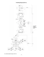
Page 22: ... 22 Form MM A4 A5SC Revised 07 13 16 Plumbing Diagram Part 1 ...

Page 23: ...E NPT 2 J 011525 00000 VALVE STEERING 1 J 006256 1 500 8 32 X 1 1 2 SLOTTED 3 J 006144 00000 8 LOCKWASHER 3 K 009070 7 000 CYLINDER AIR 2 1 2 X 7 1 L 006019 00024 ELBOW 90 DEG EXT PIPE 37 DEG 12 12 1 M 006000 00007 NIPPLE PIPE 3 4 X 3 SCH 40 GALVANIZED 2 N 011526 00000 VALVE TRAVEL 1 N 006037 2 750 HHCS 5 16 18 X 2 3 4 3 N 006148 00000 5 16 LOCKWASHER 3 O 006007 00023 CONNECTOR 37 DEG MALE PIPE 12...

Page 24: ... 24 Form MM A4 A5SC Revised 07 13 16 Plumbing Diagram Part 2 ...

Page 25: ...10 FITTING MALE ELBOW 1 4 TUBE TO 1 4 MALE NPT 3 Y 006019 00024 ELBOW 90 DEG EXT PIPE 37 DEG 12 12 4 Z 011163 00009 ADAPTER SWIVEL NUT 1 2 14 TO 1 1 16 12 1 LESS FOR A 4SC 5 AA 010925 00000 VALVE 1 LESS FOR A 4SC 5 BB 006296 00016 BUSHING REDUCER PIPE 04 02 1 LESS FOR A 4SC 5 CC 006007 00019 CONNECTOR 37 DEG MALE PIPE 08 12 1 LESS FOR A 4SC 5 DD 006032 00006 END HOSE 37 DEG FEM SWIV BARBED 12 2 LE...

Page 26: ... 26 Form MM A4 A5SC Revised 07 13 16 Plumbing Diagram Part 3 ...

Page 27: ...E MALE PIPE BARBED 06 08 3 J 006032 00002 END HOSE 37 DEG FEM SWIVEL BARBED 08 3 K 006019 00012 ELBOW 90 DEG EXT PIPE 37 DEG 06 08 3 L 010829 00009 FITTING MALE ELBOW 1 4 TUBE TO 1 8 MALE NPT 1 M 002880 00000 REGULATOR AIR 1 N 006471 00001 PLUG SUPPLIED WITH 002880 00000 AIR REGULATOR 1 O 010836 00007 FITTING STRAIGHT FEMAL CONNECTOR 1 4 TUBE TO 1 4 NPT 2 P 007059 00001 AIR GUAGE LOW PRESSURE 1 Q ...

Page 28: ... 28 Form MM A4 A5SC Revised 07 13 16 ...

Page 29: ... 29 Form MM A4 A5SC Revised 07 13 16 ...

Page 30: ... 30 Form MM A4 A5SC Revised 07 13 16 ...

Page 31: ... 31 Form MM A4 A5SC Revised 07 13 16 ...

Page 32: ... 32 Form MM A4 A5SC Revised 07 13 16 ...

Page 33: ... 33 Form MM A4 A5SC Revised 07 13 16 ...

Page 34: ... 34 Form MM A4 A5SC Revised 07 13 16 ...

Page 35: ... 35 Form MM A4 A5SC Revised 07 13 16 ...

Page 36: ... 36 Form MM A4 A5SC Revised 07 13 16 ...

Page 37: ... 37 Form MM A4 A5SC Revised 07 13 16 ...

Page 38: ... 38 Form MM A4 A5SC Revised 07 13 16 ...

Page 39: ...HYDRAULIC AR17 25 E 010941 00000 EYEBOLT 1 F 008764 00000 CYLINDER ROD EYE 1 G 006036 1 250 HHCS 1 4 20 X 1 1 4 GR 5 1 G 006402 00000 LOCKNUT 1 4 20 1 H 010943 00000 LEVER BLANK 1 I 008764 00000 CYLINDER ROD EYE 1 J 006654 00000 NUT HEX 10 24 NC THREAD 1 K 010954 00000 EYEBOLT 1 L 010942 00000 EYEBOLT 1 M 006256 0 250 RHMS 8 32 X 1 4 SLOTTED 2 M 006144 00000 LOCKWASHER 8 2 N 010955 00000 DRAW LATC...

Page 40: ...006072 00000 NUT HEX 3 8 16 2 D 006038 1 250 HHCS 3 8 16 X 1 1 4 GR 5 4 D 006072 00000 NUT HEX 3 8 16 4 E 0A6961 00000 WELDM T ADJUSTMENT 1 F 0A6965 00000 WELDM T GUIDE BRACKET 1 G 002042 00000 ISOLATOR 1 G 006071 00000 NUT HEX 5 16 18 1 G 006148 00000 LOCKWASHER 5 16 1 H 008479 00001 PIN TAB LOCK 1 I 006037 5 000 HHCS 5 16 18 X 5 GR 5 1 I 006071 00000 NUT HEX 5 16 18 1 I 006148 00000 LOCKWASHER 5...

Page 41: ...sure safety device See WARNING note below ADJUSTMENT 1 Before turning on system air pressure turn regulator adjustment counterclockwise until all load is removed from regulating spring 2 Turn on system air pressure 3 Turn regulator adjustment clockwise until the desired outlet pres sure is reached 4 To avoid minor readjustment after making a change in pressure setting always approach the desired p...

Page 42: ...r or gauge Use of Teflon tape is not recommended OPERATION ADJUSTMENTS After the regulator is installed back off pressure by adjusting T handle counter clockwise before the air is turned on Turn on air supply and adjust T handle clockwise until the pressure gauge shows desired pressure To lock the T handle tighten lock nut on adjustment screw MAINTENANCE On detection of air leaks pressure fluctuat...

Page 43: ...y the arrow 4 Install the same pipe size unit as the pipeline in use Avoid using fittings couplings etc that restrict the airflow or baffle the oil out of the air at the lubricator outlet 5 The lubricator may be filled under pressure by slowly removing the fill plug and pouring oil into the bowl through the fill tube The tank may be taken off after the fill plug is removed Do not replace the fill ...

Page 44: ... 44 Form MM A4 A5SC Revised 07 13 16 ...

Page 45: ...3 005392 01 04 BEARING DRIVE END 1 4 005392 01 05 DOWEL PIN 4 5 005392 00003 BODY GASKET 2 6 005392 01 08 KEY 1 7 005392 00004 PUSH PIN 4 8 005392 00005 VANE SPRING 8 9 005392 00006 VANE 8 10 005392 01 10 BEARING DEAD END 1 11 005392 00007 END CAP GASKET 1 005392 01 13 FELT 1 005392 00002 SERVICE KIT 1 Parts included in service kit 005392 00002 ...

Page 46: ... 46 Form MM A4 A5SC Revised 07 13 16 ...

Page 47: ... 47 Form MM A4 A5SC Revised 07 13 16 ...

Page 48: ... 48 Form MM A4 A5SC Revised 07 13 16 ...

Page 49: ... 49 Form MM A4 A5SC Revised 07 13 16 ...

Page 50: ... 50 Form MM A4 A5SC Revised 07 13 16 ...

Page 51: ... 51 Form MM A4 A5SC Revised 07 13 16 ...

Page 52: ... 52 Form MM A4 A5SC Revised 07 13 16 ...

Page 53: ...tool WARNING Always disconnect the air supply before changing steel or dismantling the tool for service or repair For maximum safety we advise the installation of a shut off valve at the end of the air line Specifications Net Weight 51lbs 23kg Blows Per Minute 2300 Chuck Size 7 8 x 4 1 4 22 2mm x 107 9mm Air Inlet NPT 3 4 19 1mm Air Consumption 92 2cfm 2 6m3 min ...

Page 54: ...00051 RIFLE BAR 1 52 009350 00052 ROTATION PAWL 4 53 009350 00053 PAWL PLUNGER 4 54 009350 00054 PAWL SPRING 4 55 009350 00055 RATCHET RING 1 56 009350 00056 RIFLE NUT 1 57 009350 00057 PISTON 1 58 009350 00058 ROT SLEEVE 1 X 4 1 4 2 5cm X 10 8cm 1 59 009350 00059 SLEEVE BSG 1 HEX X 4 1 4 2 5cm HEX X 10 8cm 1 59A 009350 0059A SLEEVE BSG 7 8 HEX X 4 1 4 2 2cm X 10 8cm 1 61 009350 00061 SLEEVE NUT 1...

Page 55: ...1 2 13 X 4 GR 5 4 C 006406 00000 LOCKNUT 1 2 13 4 D 0A9999 00004 WELDM T LIFT ANCHOR ADAPTOR 1 E 0A9958 00000 WELDM T DRILL BED EXTENSION TUBE 1 F 007102 00002 CHAIN 3 16 CLOSE LINK 13 F 006038 1 250 HHCS 3 8 16 X 1 1 4 GR 5 1 F 006106 00000 FLATWASHER 5 16 3 F 006404 00000 LOCKNUT 3 8 16 2 F 006038 1 750 HHCS 3 8 16 X 1 3 4 GR 5 1 G 006038 1 500 HHCS 3 8 16 X 1 1 2 GR 5 3 G 006106 00000 FLATWASHE...

Reviews: