miniDSP Ltd, Hong Kong /
/ Features and specifications subject to change without prior notice
11
Table 4 summarizes the relation between the clocks for the 96 kHz plugin.
Table 4. I2S clock ratios
Plugin sample rate (LRCLK) Master clock (MCLK) Bit clock (BCLK) MCLK/LRCLK BCLK/LRCLK
96 kHz
24.576 MHz
6.144 MHz
256
64
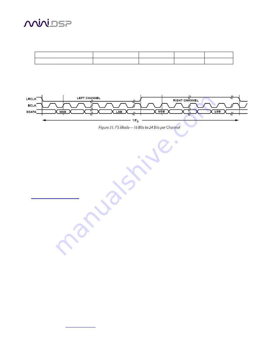
The timing of data lines is determined by the bit clock and the word clock, as illustrated in the following diagram:
The nanoSHARC board has four I2S input data lines and four I2S output data lines, each carrying two channels of
audio. Note, however, that the input data lines for channels 3 through 8 (I2S_IN1, I2S_IN2, and I2S_IN3) are not
used by current plugins.
2.7
I2S
DETAILS
The nanoSHARC acts in
master
mode with respect to I2S clocking.
That is, the nanoSHARC provides the I2S clocks and the connected devices are expected to transmit and receive
data using those clocks. The clocks will match the sample rate of the plugin loaded onto the nanoSHARC. (See
the
for more information about I2S master and slave modes). A typical connection
scenario is shown in Figure 1. Note that:
1.
The connected devices may or may not use MCLK. This is dependent on the specifics of the devices.
2.
The digital optical and asynchronous USB audio inputs use an onboard asynchronous sample rate
convertor to convert the incoming sample rate to the
nanoSHARC’s
clock domain.
3.
External digital input circuitry will need to use an asynchronous sample rate convertor to convert the
incoming sample rate to the nanoSHARC’s clock domain.


