Minicom Smart CAT5 Quick Installation Manual Download Page 7

QUICK INSTALLATION GUIDE 

6


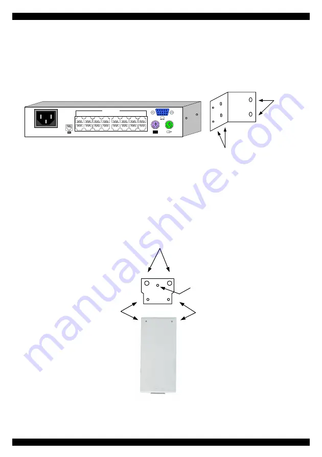
12. Rack mounting the Smart CAT5 

Make sure that the screws used for connecting the bracket to the Smart CAT5 unit, do 
not exceed 5mm. 

Use the L-shaped brackets and screws provided to mount the Smart CAT5 on a server 
rack as illustrated below. 

Insert
screws to
connect to
rack

Insert screws to connect
to Switch side panel

POWER

100-250 VAC 50/60 Hz

1

2

3

4

5

6

7

8

10

11

12

13

14

15

16

9

COMPUTER

www.

m

ini

co

m.
co

m


13. Rack mounting the RICCs 

You can attach the RICCs to a server rack or computer using the Velcro strips 
provided. Or connect it using the bracket provided. 

The figure below illustrates the bracket. 

Insert screws through
bracket and into the
back of the RICC

Insert screws through
bracket and into the
back of the RICC

Insert screws through
bracket and into the
rack

Insert screw through
bracket and into the
back of a computer


Summary of Contents for Smart CAT5

Page 1: ...el 41 1 823 8000 info europe minicom com Italy Rome Tel 39 06 8209 7902 info italy minicom com www minicom com Customer support support minicom com 5UM20113 V1 4 4 04 Smart CAT5 Switch 8 and 16 Port Q...

Page 2: ...ents The Smart CAT5 system consists of Smart CAT5 switch 8 or 16 port Remote Interface Connection cables RICCs PS 2 SUN USB CAT5 cables 1 5m provided RS232 Serial cable Rack mounts for the Smart CAT5...

Page 3: ...e that the maximum distance between each computer and the Smart CAT5 does not exceed 10m 33ft 6 Connecting the Smart CAT5 system Connect each computer to the Smart CAT5 system using the appropriate RI...

Page 4: ...ed below Connecting a PS 2 RICC Figure 4 illustrates the RICC To computer s keyboard port CAT5 cable to Smart CAT5 Computer port To computer s mouse port To computer s Video card RICC Figure 4 PS 2 RI...

Page 5: ...e RICC s RJ45 port 2 Connect the other connector to one of the Smart CAT5 s Computer ports 3 Follow the above 2 steps for each computer 7 Connecting the power supply 1 Connect the Smart CAT5 to the po...

Page 6: ...The OSD is also the place to adjust various settings as explained in the softcopy User Guide located on the Marketing and Documentation CD When switching computers the illuminated LED of the top row...

Page 7: ...tch side panel POWER 100 250 VAC 50 60 Hz 1 2 3 4 5 6 7 8 10 11 12 13 14 15 16 9 COMPUTER www minicom com 13 Rack mounting the RICCs You can attach the RICCs to a server rack or computer using the Vel...

Page 8: ...rl Alt F1 Props Left Ctrl Alt F3 Front Left Ctrl Alt F5 Open Left Ctrl Alt F7 Find Left Ctrl Alt F9 Again Left Ctrl Alt F2 Undo Left Ctrl Alt F4 Copy Left Ctrl Alt F6 Paste Left Ctrl Alt F8 Cut Left C...

Reviews: