

QUICK START GUIDE
4
9.1.1 Connecting a ROC PS/2
You can connect the ROC PS/2 to a powered on computer, but it must be in the
following order:
1. Connect the Mouse connector to the computer’s Mouse port.
2. Connect the Keyboard connector to the computer’s Keyboard port.
3. Connect the Screen connector to the computer’s Video port.
Failure to connect in the above order while the server is running, may lead to the
mouse malfunctioning until the server is rebooted.
9.1.2 Connecting a ROC USB
The ROC USB supports Windows 98 SE and later, MAC, SUN and SGI, and all
modern Linux distributions.
To connect the ROC USB:
1. Connect the Screen connector to the computer’s Video port.
2. Connect the USB connector to the computer’s USB port.
9.2 Connecting to the network
Connect the network cable to the LAN port of the Smart 216 IP. This must be done
before powering on the Smart 216 IP.
9.3 Connecting the CAT5 cables
1. Connect one connector to the ROCs RJ45 port.
2. Connect the other connector to one of the Smart 216 IP’s Computer ports.
3. Follow the above 2 steps for each computer.
9.4 Connecting a KVM console
To operate the system locally, connect a KVM console to the Smart 216 / 232 IP:
1. Connect the monitor’s connector to the Smart 216 / 232 IP’s Monitor port.
2. Connect the keyboard’s USB connector to the Smart 216 / 232 IP’s USB
Keyboard port.
3. Connect the mouse’s USB connector to the Smart 216 / 232 IP’s USB Mouse
port.
SMART 216 / 232 IP
5
9.5 Connecting the power supply
1. Using the Power cord provided, connect the Smart 216 IP to a socket outlet with
grounding connection. Only use the power cord supplied with the unit.
2. Switch on the Smart 216 IP.
10. Setting the IP address
By default, Smart 216 IP boots with an automatically assigned IP address from a
DHCP (Dynamic Host Configuration Protocol) server on the network. The DHCP
server provides a valid IP address, gateway address and subnet mask.
You can identify the IP address from the OSD at the local position. Also where
there is no DHCP server, set the IP address locally via the OSD as follows:
1. From the local keyboard, press
Shift
twice. The OSD Main window appears.
See Figure 6.
Figure 6 OSD Main window
2. Press
F2
. The Settings window appears see Figure 7.
Figure 7 Settings window
QUICK START GUIDE
6
In the
Settings window navigate downwards using the Tab key. At the bottom of
the window, press tab to go to the top of the window. Change settings by typing in
the selected area or by pressing the spacebar – whichever is relevant.
11. The OSD
You operate the Smart 216 / 232 IP system locally via the OSD.
To display the OSD:
1. From the local keyboard, press the left Shift key twice. The OSD Main window
appears. See Figure 8. Lines with the sun icons in the PM column show
switched on active computers/servers. A switched off computer has no sun icon.
When a server is busy the entire line appears in red characters.
Port number
appears here
Instruction
keys
PM=Power
management
Figure 8 OSD Main window
11.1 Navigating the OSD Main window
To navigate up and down use the Up and Down arrow keys.
To exit the OSD press
Esc
.
11.2 Selecting a computer
To select a computer:
1. Navigate to the desired computer line.
Or, type the two-digit port number of the desired computer.
2. Press
Enter
. The selected computer is accessed. A Confirmation label appears
showing which computer is accessed.
SMART 216 / 232 IP
7
12. Logging into the web interface
To complete the initial setup via the web configuration interface:
1. Open your web browser (Internet Explorer version 6.0 or higher).
2. Type the Smart 216 / 232 IP system IP address – http or https://
IP address
/ -
and press
Enter
. The login page appears.
3. Type the default Administrator user name
-
admin
-
and password
- access
-
(both lower case).
4. Press
Enter
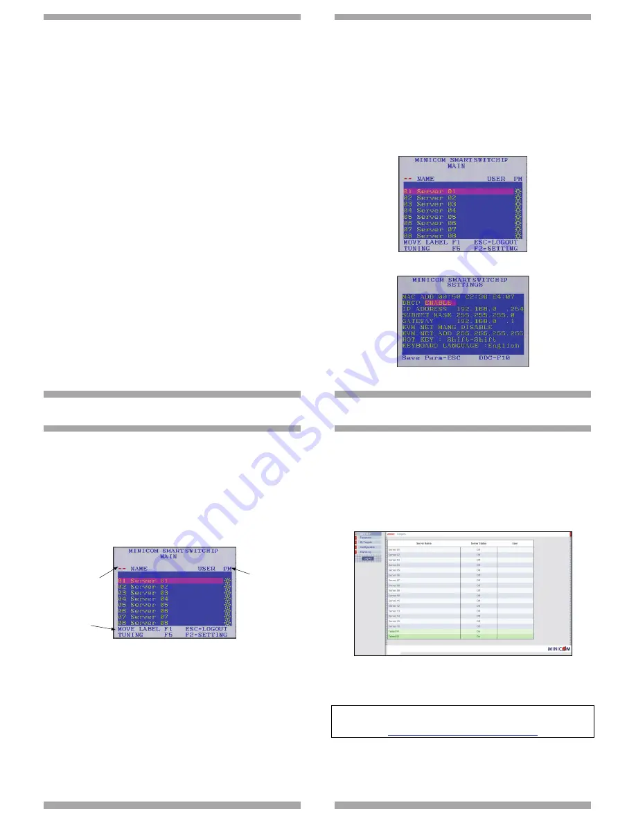
. The web interface opens at the Targets page. See Figure 9.
Figure 9 Targets page
5. To connect to a Target you click the desired Target in the Server Name Column.
For the rest of the configuration and operating instructions please see the softcopy
User Guide on the supplied CD or on our website
http://www.minicom.com/supportuserguides.htm


