4.2.8
Connecting Peripheral Devices
-
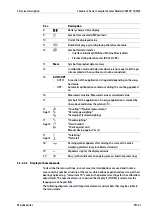
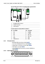
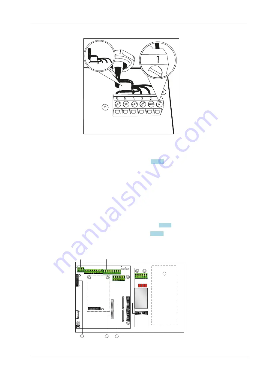
Interface Pin Assignments (see chapter
)
-
Pin Assignment Chart (see chapter
4.2.8.1
Interface Pin Assignments
Digital PCB
Com 1
1
PS/2
4
3
2
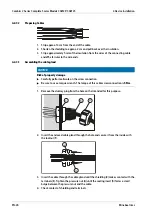
5. Insert all cores of the cable through the ferrite sleeve and, with one turn around the
ferrite sleeve, insert all cores through the ferrite sleeve again.
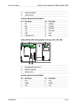
6. Screw the wires of the interface cable tightly to the terminals as per the terminal
assignment diagrams (see Chapter
).
7. For the assignment of colors/signals, refer to the operating instructions/data sheet
for the weighing platform. Any unused cables must be properly insulated.
8. When connecting a load receptor using the 4-cable method (weighing platform cable
to be connected has only 4 wires), connect terminal pairs 1 and 2 (EXC+ and SENSE+)
and 5 and 6 (SENSE- and EXC-) using a wire jumper.
9. After completion of the assembly work, use a pressure gauge to check the IP69K
protection. For further information, please contact Minebea Intec Service.
4 Device installation
Combics 2 Series Complete Scales Models CAW2P, CAW2S
Minebea Intec
EN-29

