


8
In addition, the DI-PORT can receive a 44.1-kHz signal and at the same time send a 48-kHz
signal, or vice versa. For this purpose, the DI-PORT must be set to master mode. With this
option, two devices can actually be operated as masters. In this case, the DI-PORT
operates in slave mode on the receiving side and uses the incoming signal’s sampling
rate. On the send side, it is in master mode and routes the outgoing signal at the selected
frequency. These frequencies may not coincide.
Although it is possible, we recommend that you refrain from running two devices as
masters.
2. Control Features
In keeping with the signal flow in the device, the control features of the DI-PORT are
arrayed from left to right.
2.1 Preamplifiers
Mic/Line In: XLR input designed to take
microphones. The pin assignments of this
XLR socket comply with the international
norm IEC 268-12. In accordance with this
standard, Pin 1 is connected to the
ground, Pin 2 carries the positive signal
and Pin 3 the negative signal. If you use
this multi-purpose socket as a 1/4” jack plug, you can also insert line signals to it.
Green LED: This indicator lights up whenever a signal is routed to the input.
Red Peak LED: This indicator lights up to indicate the signal is clipping . In this case, use
the Gain knob to back off the input level.
Gain: Adjust the input level for the line or microphone inputs of the DI-PORT here. To fine-
tune and visually monitor levels, check out recording level meter of the digital device that
follows the DI-PORT in your signal chain. The peak LED of the DI-PORT indicates a
saturated signal, be sure it does not light up.
2.2 Input Selection and Phantom Power
Front/Rear: This button routes the micro-
phone/line inputs on the front panel or
the line inputs on the rear panel of the
DI-PORT to the A/D converter.
48 V: This button switches phantom power on, which is then fed to the connected
microphone. Dynamic microphones don't require phantom power. When you use capacitor
microphones, be sure to press this button.
2.3 Monitor Section
Mix: The monitor and headphones output patch out
a mix of the digital and analog input signal of the
DI-PORT. The Mix knob lets you blend these signals
to dial in the desired balance.
Volume: Use this knob to dial in the desired level for the headphones and monitor signal
Phones: Connect headphones here.
3. Rear Panel of the DI-PORT
3.1 Analog Connections
Analog In: These are 6.3 mm (1/4") input jacks
designed to take unbalanced line signals. You may
connect high-level signal sources such as
synthesizers, mixer outputs, the recording output
of a guitar amp, and the like here.
D/A Out: These two analog outputs route out the left and right channels of the signal that
is inserted into the digital input of the DI-PORT. This is a direct out circuit, meaning that
the Volume knob has no influence on the level of this signal.
Monitor Out: These analog outputs route out a mix of the digital and analog input signals
of the DI-PORT. Adjust the balance of signals via the Mix knob located on the front panel.
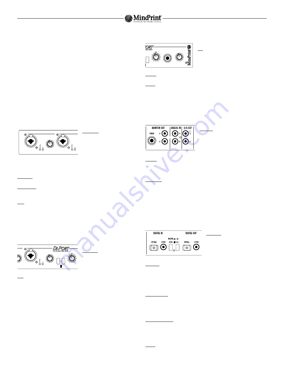
3.2 Digital Interface
The DI-PORT‘s is connected to digital circuits via an interface designed to handle coaxial
and optical S/PDIF formats.
Digital Out: Both channels of the converted
A/D input signal are routed out here.
Connect this port to the digital input of your
audio card.
Digital In: Digital input designed to convert the digital output signal of your computer into
an analog signal. The converted D/A signal is patched directly to the D/A Out port (see
above). In addition, this signal is also routed to the Monitor Out and can be blended in
with the analog input signal via the Mix knob. Connect Digital In to the digital output of
your audio card.
44.1 / 48 Button: This button selects a sampling frequency of 44.1 or 48 kHz when the
DI-PORT is operated exclusively as a A/D converter or is not receiving a valid digital input
signal. If on the other hand a valid digital signal is inserted into the digital input, the
DI-PORT adjusts its sampling rate so that it corresponds to that of the incoming signal.
Auto/Master Button: If you set the DI-PORT to Master, the device will operate with its
internal clock and its sampling frequency is determined by the 44.1/48 button. Set to Auto
mode, the DI-PORT is locked into sync with the signal routed into its digital input. The
device automatically adjust its sampling frequency accordingly.
Locked: This LED lights up as soon as the DI-PORT recognizes a valid digital signal at its
S/PDIF input.
MindPrint DI-PORT
GAIN A
5
0
3
2
4
1
6
7
8
XLR = MIC
JACK = LINE
ANALOG IN A
PEAK
ANALOG IN B
2
1
SIGNAL
XLR = MIC
JACK = LINE
PEAK
SIGNAL
FRONT
AIN A
5
4
6
7
8
48 V
ANALOG IN DIGITAL IN
GAIN B
ANALOG IN B
INPUTS
MIX
5
0
3
2
4
1
6
7
8
OFF
ON
XLR = MIC
JACK = LINE
PEAK
SIGNAL
REAR
LOCKED
48 V
ANALOG IN DIGITAL IN
PHONES
VOLUME
MIX
5
0
3
2
4
1
6
7
8
MONITOR
OFF
ON


