


2
In preparation, before installing this accessories ledge, you will need to have completed
the installation of the panel system and sealed the seams of the shower where the ledge
is to be installed with 100% silicone.
Materials and Tools required:
1. Drill, preferably corded, for drilling holes
2.
3/16” masonry drill bit
3. Measuring tape
4. Pencil
5. 100% Silicone for marble to marble seams (color matched for the marble)
6. Clean, dry cloth for the accessories ledge and the wall
7. #2 Phillips Head Screwdriver to tighten screws when attaching standoff mounting tubes
8. 2
– WingIt MAW35-SD fasteners and 2 – standoff tubes (provided by Mincey Marble)
9. Either a WingIt Apache 200 Drill Bit P/N# WA200GT34 (which may be purchased from
Mincey Marble) or a ¾” hole saw, for drilling holes for MAW35-SD Master WingIt.
IMPORTANT NOTE: The accessories ledge will be located on the same wall as the FR-05
foot rest, which is the end wall opposite from the shower head. The ledge should be
installed so that it butts against the back shower panel. It will be pre-trimmed by Mincey
Marble prior to shipping so that it will fit flush against the back wall.
Installing the Accessories Ledge:
1. The installer should measure from the trimmed end of the ledge to the first hole and
then mark the first hole that distance from the back wall, keeping the hole centered to so
that the ledge will be al
igned with the band. The second hole should be 16” forward
along the band from the first hole.
2. Pre-
drill the holes for the mounting hardware using the 3/16” masonry drill bit and the
corded drill.
3.
Insert an “L” shaped wire. Twirl the wire and make sure you don’t hit an obstruction.
If you do hit a wall stud, you can move the hole location either forward or backward up to
an inch and the ledge will still cover the other holes.
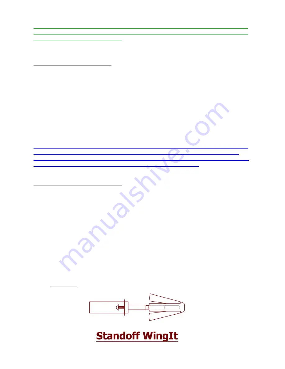
4. Assemble the mounting hardware as shown in Drawing (A).
Drawing A:


