© 2013 MIMAKI ENGINEERING CO.,LTD.
6.4.1
P.1
R.1.0
6.4.1 Main PCB assy.
Work procedures
1. Turn off the main power supply and remove the power plug
from the main body.
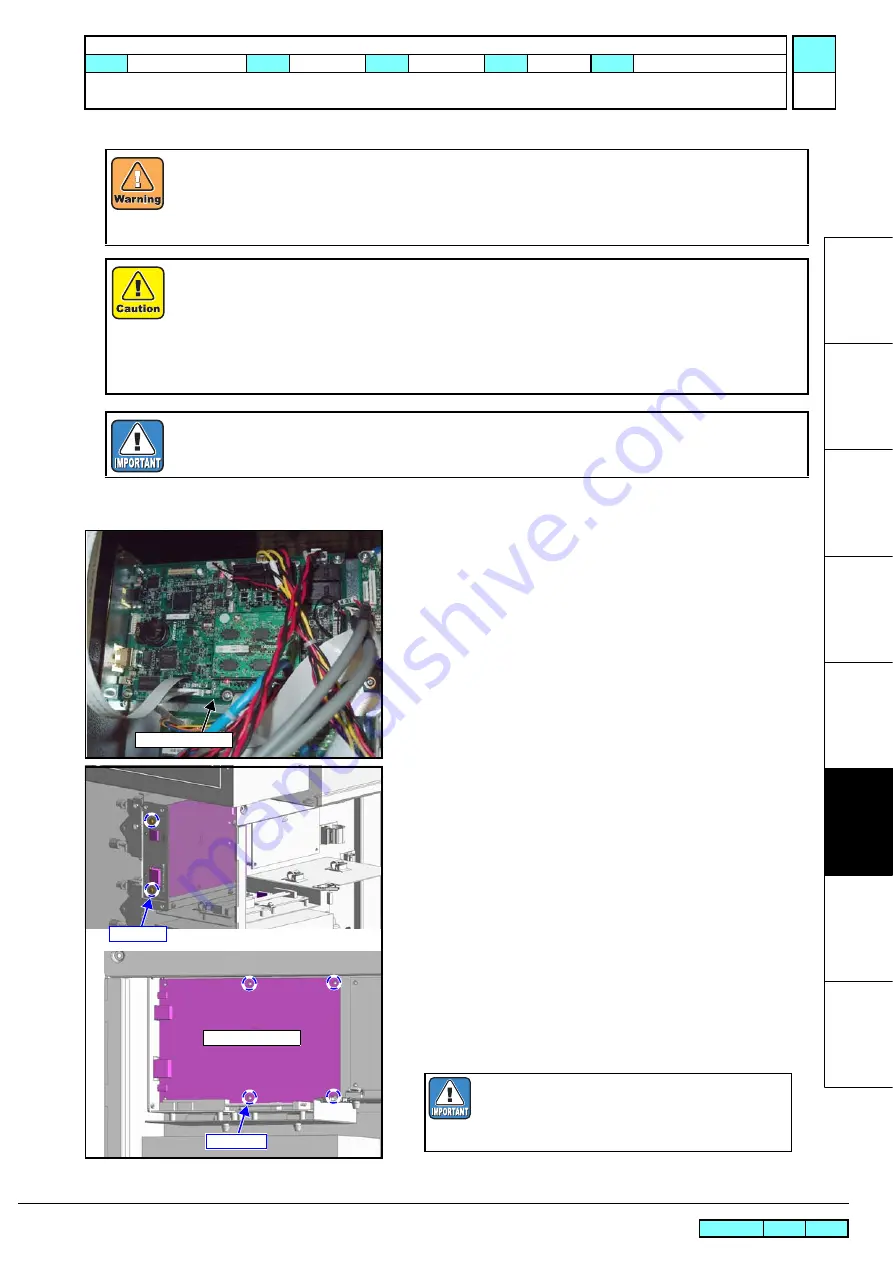
2. Open the cover RRU, and disconnect all connector on the PCB.
3. Remove the screw, and remove the
main PCB assy.
.
4. Change to mount the
memory PCB
onto the new main PCB.
5. Reverse the disassembly procedure for reassembly.
After turning off the sub and main power switches, unplug the power cord. Make sure to take 15 minutes
before restarting the operation. It is very dangerous if sleep mode functions mistakenly during the operation.
Moreover, the PCB may be damaged in case electric charge still remains inside.
Also, there is a possibility of electric shock because of high voltage applied to the high-power part of the DC
power supply assy. Take care to avoid contact with it.
A button type lithium battery is used for this board. Warn following 1)~4).
1), Danger of explosion if battery is incorrectly replaced.
2), Replace only with the same or equivalent type recommended by the manufacture.
Recommended type : [CR2032]
3), Dispose of used batteries according to the manufacturer
'
s instructions.
4),When the battery is replaced with a new one, pay attention to the polarity at replacing.
Proceed with the work after well confirmed the following processes in advance.
3.3.1 Replacement of the Main PCB assy.
Main PCB assy.
Screw(x2)
Screw(x4)
Main PCB assy.
When a used Main PCB is to be discarded,
remove the installed battery (CR2032).
Disposal of the used battery according to manu-
facturer’s instructions
MAINTENANCE MANUAL > Disassembly and Reassembly > Electrical Parts > Main PCB assy.
Model
SWJ-320S
Issued 2012.07.19 Revised
F/W ver
Remark
1.0
Summary of Contents for SWJ-320 S2
Page 209: ......
Page 210: ...D500764 12 28082013 MIMAKI ENGINEERING CO LTD 2013 WK FW 2 20 ...


