


Chapter 2 Outline explanation
2-5
2
2
2
5
6
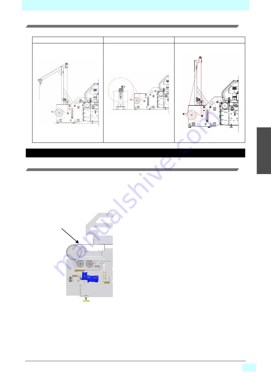
Option
The following options can be used for feeding media.
Main Parts of Machine
Main belt
The belt consists of two conveyor rollers (One is motor driven) and a rubber belt.
On the surface of the belt there is a bedding layer that makes the media that passes under the printhead completely
adhere and stabilize.
The belt moves not continuously but intermittently. When the belt stops, it prints the set image by repeating printing after 1
pass or several passes printing.
Shaking unit with centering
Big roll unit
Small roll unit with centering
Main belt
Summary of Contents for ML Tiger-1800B MKII
Page 3: ...ii 1 2 2 4 5 6 ...
Page 6: ...v Troubleshooting 9 5 Dismantling 9 27 ...
Page 25: ...Chapter 1 Introduction 1 19 1 2 3 4 5 6 M915601 PC outlet rated label ...
Page 26: ...Chapter 1 Introduction 1 20 ...
Page 38: ...2 12 Chapter 2 Outline explanation ...
Page 50: ...4 10 Chapter 4 Installation ...
Page 120: ...Chapter 6 Basic usage 6 66 ...
Page 140: ...Chapter 7 Operation Adjustment and Maintenance 7 20 ...
Page 174: ... MIMAKI ENGINEERING CO LTD 2020 IG MM Tiger Products Install Pack 2 04 ...


