Direct-Q
®
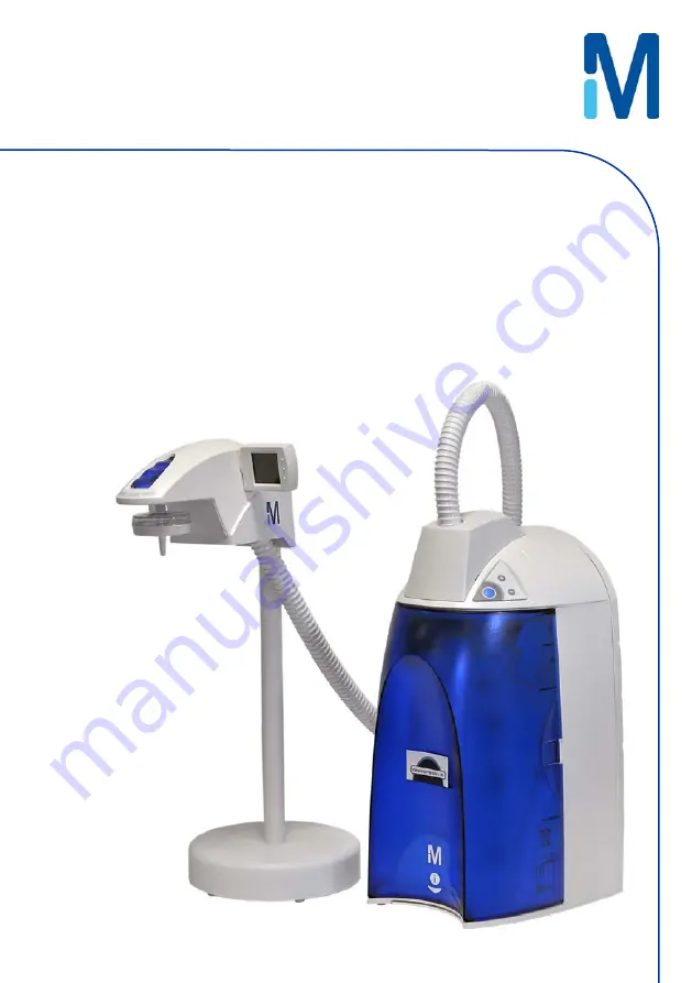
3, 5, 8 R system
Direct-Q 3, 5, 8 UV-R system
User manual
Page 1: ...Direct Q 3 5 8 R system Direct Q 3 5 8 UV R system User manual...
Page 2: ......
Page 3: ...ems are fed with water quality within specifications and properly maintained as required by the supplier We do not warrant these systems for any specific applications It is up to the end user to deter...
Page 4: ...uct should not be treated like household waste when discarded Instead the product should be disposed of at a location that handles discarded electric or electronic equipment Proper disposal of equipme...
Page 5: ...ng for a Direct Q 5 and 8 R 12 Connection of the Power Cord Turning on the System Power 15 Installation of the SmartPak cartridge 16 Flush Mode 18 Calibration of the Tank Level for a Direct Q 5 and 8...
Page 6: ...dule 43 How to Replace the SmartPak Cartridge 45 Flush Mode 47 How to Replace the Final Filter 50 How to Clean the Screen Filter 51 How to Calibrate the Tank Level C04 52 How to Empty the Tank C03 54...
Page 7: ...t to use this equipment as specified in this manual using this equipment in a different manner may impair the safety precautions of the Direct Q R System Symbol What it means This HAZARD symbol is use...
Page 8: ...illipore SAS Internet Site can be used to find addresses telephone fax numbers and other information Internet Site Address www millipore com www millipore com techservice www millipore com lab_water M...
Page 9: ...Water Specifications Water Flowrate Specifications Direct Q R System Type RO water flowrate Dispensing flowrate Reject water flowrate 5 C T 35 C Direct Q 3 R 3 LPH 15 25 C Up to 42 LPH 15 LPH to 25LP...
Page 10: ...he maintenance of the system Tap water is pretreated to protect the RO membrane from organic fouling and chlorine oxidation The RO membrane has 2 exiting streams permeate pure water and reject The per...
Page 11: ...9 kg 14 9 kg Dry Weight 10 2 kg 9 2 kg 9 2 kg 10 7 kg 9 7 kg 9 7 kg Shipping Weight 15 0 kg 14 0 kg 14 0 kg 15 5 kg 14 5 kg 14 5 kg Noise Level A Direct Q R System has a maximum noise level of 50 dB a...
Page 12: ......
Page 13: ...as CaCO3 Free Chlorine 1 ppm Langelier Saturation Index 0 2 TOC 2000 ppb Feedwater Connection Needed Feedwater Piping Connection 1 2 inch Male GAZ NPTM or BSPM Reject Flow Requirement Drain Capacity...
Page 14: ...ank The Tank Connector Kit is used to connect the 30 L tank to the system The mounting hardware for connecting the external tank to the system is not included and must be supplied The Millipore SAS Ca...
Page 15: ...e tie wrap B Remove and pull the tie wrap out C Locate the protective foam found at the UV lamp cable Remove it C Connection of Tubing for a Direct Q 3 R Go directly to section Connection of tubing fo...
Page 16: ...s the Feedwater source Apply white tape on the thread of the 1 2 inch Male GAZ valve or fitting of the Feedwater source C Connect the fitting to the valve C Reject Tubing D Locate the Reject Tubing ex...
Page 17: ...and the adaptor fitting in the Accessories Bag Install the Tank Outlet Valve and Pure Permeate Tubing as shown F G and H G H I Open the Tank Outlet Valve I This allows the tank to be emptied of any wa...
Page 18: ...1 A 1 2 inch Female GAZ fitting with a screen filter is attached at the end of this tubing Unroll it until the fitting reaches the Feedwater source Apply white tape on the thread of the 1 2 inch Male...
Page 19: ...Installation 13 Connection of the Ultrapure Type 1 water dispenser 1 Locate the Ultrapure Type 1 water dispenser The Ultrapure Type 1 water dispenser and the water system come separately...
Page 20: ...ote dispenser to the water system black tubing on black tubing and transparent tubing on transparent one 3 Connect the 2 electrical connectors Molex Picoflex to the PC Board 4 Make sure the system ope...
Page 21: ...e system is powered B Plug the Power Cord into the system B Plug the other end of the Power Cord into an appropriate source of electrical power i e wall outlet The system is immediately powered Open t...
Page 22: ...A HAZARD Do not touch the UV Lamp when replacing the SmartPak cartridge Installation A Make sure the front cover is opened B STANDBY should be viewed on the Display B Remove the SmartPak cartridge fro...
Page 23: ...llation 17 D Install the SmartPak cartridge E Check that the SmartPak Cartridge it is fully seated into the system ports as shown F CLOSE THE FRONT COVER G NOTE The Tank Outlet Valve should be left op...
Page 24: ...ld be left open during FLUSH mode H The system will now go into FLUSH mode for 15 minutes H This is done to empty the SmartPak cartridge of air and hydrate the material inside I When FLUSH mode is fin...
Page 25: ...a full Reservoir and which Signal voltage represents an empty Reservoir NOTE The TANK LEVEL Calibration is used to calibrate the Level Sensor Signal Voltage relative to the water level inside the Res...
Page 26: ...e Display will show the lowest Tank Level red level display blinking NOTE The highest and lowest tank level must be calibrated together or else the tank level is not calibrated 6 Move the Float on the...
Page 27: ...ve the system in FILLING TANK overnight to ensure complete rinsing of the RO membrane Close the Tank Outlet Valve J and connect it back to the system if needed The tank will start to fill up with wate...
Page 28: ...te the clear Tygon Tubing and the Barbed Fitting from the Accessories Bag Screw the Barbed Fitting onto the bottom end of the POU Dispenser C D Push one end of the Tygon Tubing onto the end of the Bar...
Page 29: ...ged from the system Verify that you have a full tank of RO water by viewing the Tank Level display A B Press the Dispensing Button once to put the system into DISPENSING mode B C Dispense the full tan...
Page 30: ...media inside the SmartPak cartridge Do not leave the system in STANDBY mode The next morning Press the Dispensing Button once to put the system into DISPENSING mode Allow about 1 Litre of water to be...
Page 31: ...NG mode Locate the air vent valve not present on all types of Final Filters on the top side of the Final Filter Open this slowly but do not remove it B Allow any air on the clear side of the Final Fil...
Page 32: ...r the menu The Display will show F01 2 Press the Main Button once The Display will show F02 and the 60 second timer The graduated cylinder will be blinking 3 Press the Dispensing Button once The syste...
Page 33: ...n Litres dispensed from the system using a 1 L graduated cylinder 5 Press the or Button to match the volume Display to the volume measured 6 To exit the menu press and hold the Main Button for 2 secon...
Page 34: ...easurements that would be seen if the water temperature was 25 C 1 Press the Main and Buttons together to enter the menu The Display will show C01 and the units chosen The following Display shows Temp...
Page 35: ...n 29 4 Press the or Button to select Non Temperature Compensated Conductivity Units S cm 5 To exit the menu press and hold the Main Button for 2 seconds To display the next menu option press the Main...
Page 36: ...together to enter the menu The Display will show C01 2 Press the Main Button once The Display will show C02 and the Resistivity Setpoint value 3 Press the or Button to adjust the Resistivity Setpoint...
Page 37: ...Installation 31 4 To exit the menu press and hold the Main Button for 2 seconds To display the next menu option press the Main Button once...
Page 38: ......
Page 39: ...0 UV System only How to Get Water from the Direct Q R Product Water Using the Dispensing Button There are two ways to get water using the Dispensing Button Press once and release OR Press and hold dow...
Page 40: ...front of your reservoir How to Dispense an Exact Amount of Product Water F01 1 Press the Main and Buttons together to enter the menu The Display will show F01 2 Press the or Button to adjust the exac...
Page 41: ...press and hold the Main Button for 2 seconds To display the next menu option press the Main Button once The Direct Q water systems has been designed to operate permanently connected to feed water plu...
Page 42: ...alled and the front cover has been closed FLUSH mode allows tap water to enter and rinse the new SmartPak cartridge The Tank Outlet Valve must be opened during the FLUSH cycle to keep the tank from fi...
Page 43: ...tion during FILLING TANK mode Pre Operate PRE OPERATE mode is displayed when the system is not dispensing water and not in FILLING TANK mode The Tank Level display is between the 60 level and TANK FUL...
Page 44: ...spensing The resistivity and temperature remain displayed for up to 10 seconds after dispensing is stopped Auto Dispensing AUTO DISPENSING mode is displayed when selecting menu option F01 AUTO DISPENS...
Page 45: ...conductivity value that was measured during Filling Tank mode The displayed value is not a real time value It is the last permeate conductivity value memorized after the system was in Dispensing Mode...
Page 46: ...on C02 When the red Pack Alarm is displayed as a steady icon the SmartPak cartridge is not installed correctly or not installed at all If the SmartPak cartridge has been reinstalled and the Alarm is s...
Page 47: ...mode starts the tank has to be emptied of water The FLU counter display will be blinking if the system has detected that there is water in the tank The Tank Outlet Valve must be opened The system will...
Page 48: ......
Page 49: ...laced when the SmartPak cartridge is replaced or when the Product Water flowrate drops See Section How to Replace the Final Filter Vent Filter Replacement Replaced when the SmartPak cartridge is repla...
Page 50: ...How to Clean the Screen Filter Sanitization of the System Once a year The SmartPak cartridge will have to be replaced after the sanitization of the system See Section How to Empty the Tank C03 and Ho...
Page 51: ...rtridge is rinsed out A HAZARD Do not touch the UV Lamp when replacing the SmartPak cartridge Removing the SmartPak cartridge A Open the front cover to go into STANDBY mode Wait for the system to depr...
Page 52: ...n the ports of the SmartPak cartridge Locate the O rings on the ports Wet them with water It is preferable to wet them with ultrapure water Install the SmartPak cartridge until it is fully seated into...
Page 53: ...laced to the drain This will completely rinse the purification media inside the SmartPak cartridge NOTE for sensitive applications it is recommended to leave the system in FILLING TANK overnight to en...
Page 54: ...should be replaced whenever the SmartPak cartridge is replaced Remove the Vent Filter K Insert the new Vent Filter into the fitting See Section Installation of the Vent Filter Installing the Tygon Tu...
Page 55: ...Maintenance 49 Hydrating the System M Hydrate the system M See Section Hydrating the System Replacing the Final Filter N See Section How to Replace the Final Filter N The System is now ready for use...
Page 56: ...inside which provides a watertight seal B If your Final Filter is a Millipak Locate the air vent valve on the top side of the Millipak Open this slowly but do not remove it from the Millipak B Allow a...
Page 57: ...Feedwater 8 mm OD Tubing originates Unscrew the collar that holds the Feedwater Tubing to the barbed end of the fittings A Pull the tubing off of the fitting Unscrew the Screen Filter from the Feedwa...
Page 58: ...the Main Button 3 times The Display will show C04 The highest Tank Level display will be blink ing This means that the highest water level is ready to be calibrated 3 Press the and Buttons together to...
Page 59: ...ether to enter the lowest water level The Display will exit the menu option and go into FILLING TANK mode The Tank Level is now calibrated NOTE If the Display remains in the menu option and the highes...
Page 60: ...e other end of the Tygon Tubing in a sink 1 Press the Main and Buttons together to enter the menu The Display will show C01 2 Press the Main Button 2 times The Display will show C03 3 Press the and Bu...
Page 61: ...e tank will also be sanitized You will need a minimum Tank Level display of at least 50 A B Locate the clear elbow fitting the clear tubing and the syringe in the Sanitization Kit B You will need 200...
Page 62: ...ilter and install the clear elbow fitting from the Sanitization Kit D E Introduce the male connector of the clear tubing firmly into the elbow fitting E F Inject 200 ml 1 ml 1 cc of Hydrogen Peroxide...
Page 63: ...H Let the tank fill up to the 100 level H I Let the system stand for 1 hour for effective bacteria elimination After 1 hour Remove the Final Filter Install the Barbed Fitting and Tygon Tubing I J Per...
Page 64: ...e 100 level K L Perform an EMPTY TANK C03 again to dispense all the water in the tank L M Open the front cover to let the system go into STANDBY mode M The SmartPak cartridge the Vent Filter and the F...
Page 65: ...then you do not need to perform a tank sanitization You will need a minimum Tank Level display of at least 50 A B Locate the clear elbow fitting the clear tubing and the syringe in the Sanitization K...
Page 66: ...ll the clear elbow fitting from the Sanitization Kit D E Introduce the male connector of the clear tubing firmly into the elbow fitting E F Inject 200 ml 1 ml 1 cc of Hydrogen Peroxide solution 30 int...
Page 67: ...Maintenance 61 G Close the front cover G The system will now go into FILLING TANK mode H Let the Tank Level display go up to the 100 level H Continued on next page...
Page 68: ...the tank J K Close the Tank Outlet Valve K L Close the front cover L The system will now go into FILLING TANK mode Let the tank level fill up to the 100 level Repeat steps I J K and L Open the front c...
Page 69: ...er has reached 0 days see Section How to View or Reset the UV Lamp Timer C05 HAZARD No electrical power should be going to the system at this time Accidental exposure to ultraviolet light can cause da...
Page 70: ...a manner that is environmentally safe D Detach the Velcro belt of the UV housing Pull the UV housing out so that the UV Lamp cable is accessible D NOTE Use the gloves supplied with the UV replacement...
Page 71: ...u use the gloves supplied with the UV replacement kit Carefully insert the UV Lamp into the UV housing G H Plug the electrical cable to the new UV Lamp H I Attach the UV housing with the Velcro belt I...
Page 72: ...l the old SmartPak cartridge BEFORE powering ON the system Otherwise the system will go into FLUSH mode for 15 minutes during which no Product Water will be available Close the front cover Plug the el...
Page 73: ...red UV Lamp Alarm icon blinking when the Timer reaches 0 days This message is displayed until the UV Lamp is replaced and the UV Lamp Timer is reset How to View the Remaining Days on the UV Lamp Timer...
Page 74: ...together to enter the menu The Display will show C01 2 Press the Main Button 4 times The Display will show C05 and 0 days left on the UV Timer 3 Press the and Buttons together This will reset the UV T...
Page 75: ...k Filter is air locked Final Filter is clogged Allow the system to go into FILLING TANK mode until there is enough water available in the tank viewed by the Tank Level display Close the Tank Outlet Va...
Page 76: ...heck that the Tank Outlet Valve and Tubing are directed downwards into the drain The SmartPak cartridge lifetime is exhausted The Product resistivity is less than the Resistivity Setpoint set in menu...
Page 77: ...he UV Lamp UV System only After a new UV Lamp has been installed reset the UV Timer See Section How to View or Reset the UV Lamp Timer C05 UV System only The UV Lamp is not installed correctly or not...
Page 78: ......
Page 79: ...ak Final Filter V0CPAK001 EDS Pak Installation Kit ordered 1 time only for multiple EDS Pak uses EDSKIT001 Millipak Express 40 Final Filter MPGP04001 Millex Vent Filter 1 m 2 box TANKMPK03 UV Lamp 185...
Page 80: ...vering a fixed ultrapure water volume 33 Delivering ultrapure water 33 Improving ultrapure water quality by recirculation before sourcing water 39 Replacing the Millipak end filter 50 Replacing the Sm...