background image

OM-230 161 Page 8

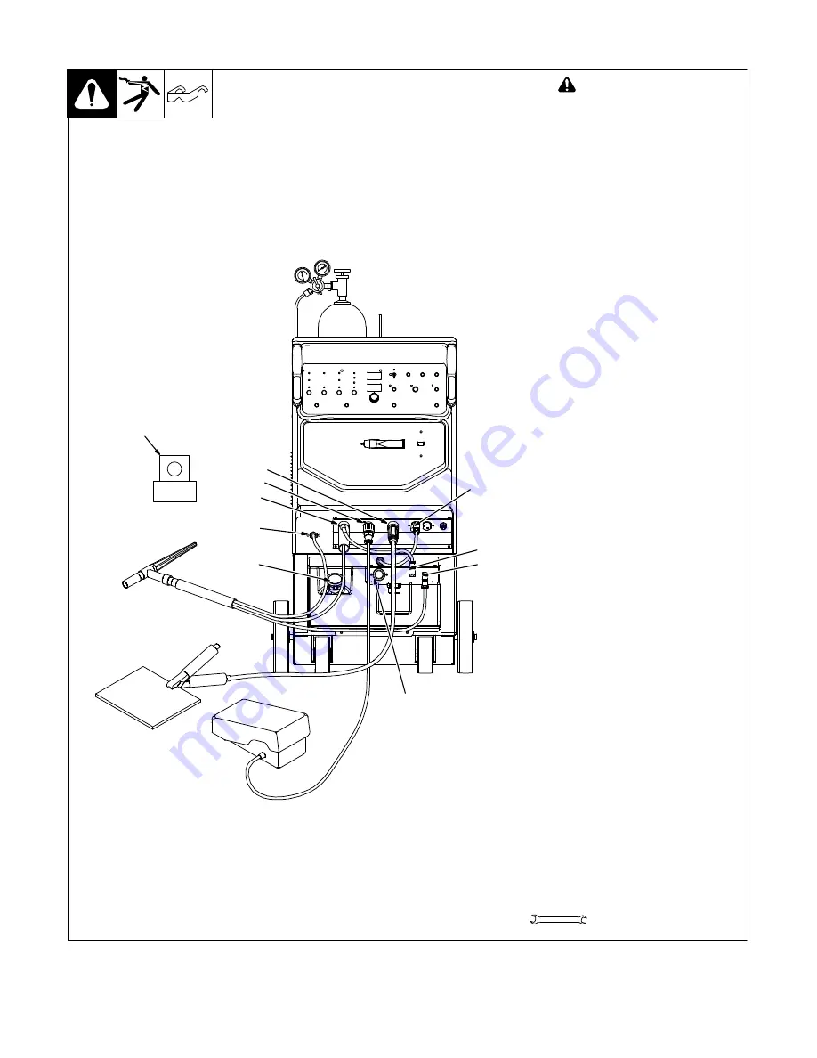
6-2. Optional Cooler Connections

 805 102-B

Tools Needed:

11/16 in. (21 mm for CE units)

!

Disconnect cooler plug from

welding power source re-

ceptacle  before filling.

1

Cap

Remove cap and fill tank with three

gallons of coolant (see Section

4-3).
2

Gas Out Connection

Connect TIG torch gas hose to gas

out fitting.
3

Electrode Weld Output

Terminal

4

TIG Block (Customer Sup-

plied)

Connect TIG torch to electrode

weld output terminal. Note: Some

models may require a TIG block

instead of the international style

water connector.
5

Remote 14 Receptacle

Connect remote control to recep-

tacle if desired.
6

Work Weld Output Terminal

Connect work lead to work weld

output terminal.
7

Water-In (From Torch)

Connection

Connect torch water-out (red) hose

to welding power source water-in

connection.

NOTICE 

 If welding power source

has a water valve, do not connect

hoses to water valve.

8

Water-Out (To Torch)

Connection

Connect torch water-in (blue) hose

to welding power source water-out

connection.

Operation:

9

115 VAC Cord

10 Flowmeter
To turn cooling unit On, connect

power cord to welding power

source 115 volts AC receptacle.

Unplug to turn unit Off.
Flow indicator spins to indicate that

at least 1.1 qt/min (1.0 L/min) of

coolant is flowing.

1

3

5

6

7

2

8

9

4

10

Summary of Contents for Cool Runner 3CS OM-230 161 F

Page 1: ...Cool Runner 3CSt Processes Description TIG GTAW Welding OM 230 161 F 2012 08 File TIG GTAW MIG GMAW Welding Visit our website at www MillerWelds com...

Page 2: ...ntinue the tradition They re just as committed to providing equipment and service that meets the high standards of quality and value established in 1929 This Owner s Manual is designed to help you get...

Page 3: ...maintenance 3 2 4 Proposition californienne 65 Avertissements 4 2 5 Principales normes de s curit 4 2 6 Informations relatives aux CEM 4 SECTION 3 DEFINITIONS 5 3 1 Additional Safety Symbols And Defi...

Page 4: ......

Page 5: ...re is properly connected to ground terminal in disconnect box or that cord plug is connected to a properly grounded receptacle outlet D Keep cords dry free of oil and grease and protected from hot met...

Page 6: ...43rd Street New York NY 10036 phone 212 642 4900 web site www ansi org Standard for Fire Prevention During Welding Cutting and Other Hot Work NFPA Standard 51B from National Fire Protection Associati...

Page 7: ...proc der l in stallation la r paration ou l entretien de l appareil D verrouiller l alimentationselon la norme OSHA 29 CFR 1910 147 voir nor mes de s curit D Installez mettez la terre et utilisez cor...

Page 8: ...George Carter Way Suite 103 Chantilly VA 20151 phone 703 788 2700 website www cganet com Safety in Welding Cutting and Allied Processes CSA Standard W117 2 from Canadian Standards Association Standar...

Page 9: ...Electronic Equipment WEEE by disposing at a designated collection facility Contact your local recycling office or your local distributor for further information Safe37 2012 05 Safe50 2012 05 Plugged f...

Page 10: ...al 11 4 L Coolant Tank Capacity Flow Rate Is 1 Liter Per Minute 1 1 Quarts Cooling Unit Dimensions 25 5 8 in 651 mm Long 19 13 16 in 503 mm Wide 10 3 4 in 273 mm High Weight 40 lb 18Kg Base Dimensions...

Page 11: ...ied Varies By Model Connect coolant hose between Coolant In fit ting and TIG block located on welding power source Electrode weld output terminal or connect international style water adapter to Electr...

Page 12: ...nector 5 Remote 14 Receptacle Connect remote control to recep tacle if desired 6 Work Weld Output Terminal Connect work lead to work weld output terminal 7 Water In From Torch Connection Connect torch...

Page 13: ...ns nCheck coolant level Every 6 Months nlHoses nl Labels ZChange coolant if using water Every 12 Months ZChange coolant if using Miller coolant 7 2 Coolant Maintenance 805 516 A 1 Disconnect cooler pl...

Page 14: ...eset if necessary Motor overheated Unit starts running when motor has cooled Have Factory Authorized Service Agent check motor Decreased or no coolant flow Add coolant Check for clogged hoses or coola...

Page 15: ...asher Flat 812 ID X1 469 OD X 134 T STL PLD ANSI 750 2 8 209 869 Wheel 2 9 233 120 Base 1 10 230 366 Label Warning General Precautionary Static 2 11 168 247 Caster Swivel 2 12 231 336 Cool Unit 3CS Se...

Page 16: ...M 230 161 Page 12 Hardware is common and not available unless listed 1 2 3 6 7 9 7 10 8 11 12 13 14 15 16 17 18 19 20 21 22 23 28 25 26 7 27 24 29 30 4 5 804 995 A Figure 9 2 Cooling Unit Main Assembl...

Page 17: ...Hose Brs Barbed Elbow M Bhd 3 8 Tbg X 500 20 2 18 204603 Label Coolant Out 1 226934 Indicator Flow Includes 1 19 186005 Lense Flow Indicator 1 20 166566 O Ring 1 301 ID X 070 CS 70 Duro Buna n 1 21 2...

Page 18: ...TM 216 869 Page 14 Dynasty 350 700 Maxstar 350 700 Notes...

Page 19: ...ontrols and Receivers Work Stations Weld Tables No Labor 5 6 Months Parts Batteries Bernard Guns No Labor Tregaskiss Guns No Labor 6 90 Days Parts Accessory Kits Canvas Covers Induction Heating Coils...

Page 20: ...your personal records Always provide Model Name and Serial Style Number Contact a DISTRIBUTOR or SERVICE AGENCY near you Welding Supplies and Consumables Options and Accessories Personal Safety Equip...

Reviews: