Description
Air Filtration Panel
OM-255447 Rev. A
2018
−
06
File: Accessory
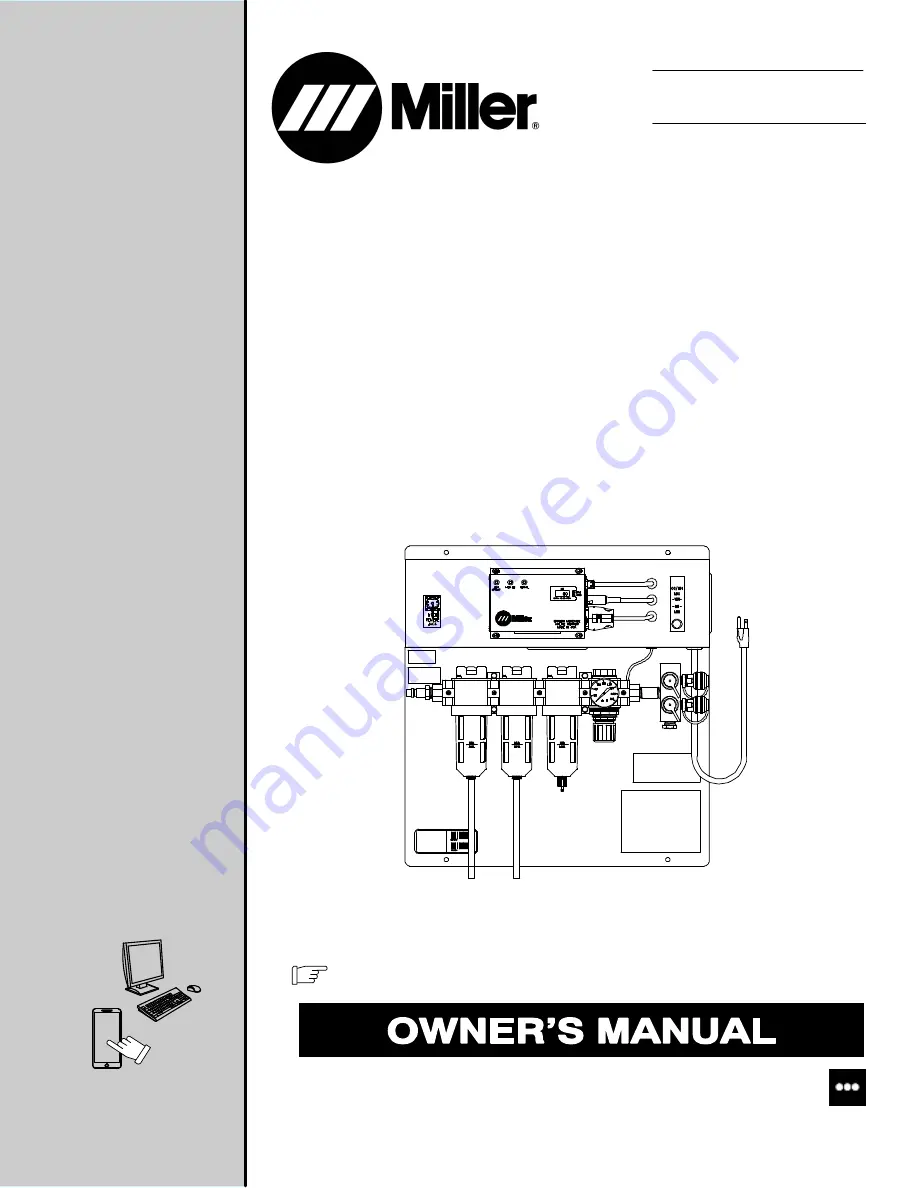
BreatheAir
t
Filtration Panel
To help us serve you better, go to www.MillerWelds.Com/Register
For product information,
Owner’s Manual translations,
and more, visit
www.MillerWelds.com


