OM-4422 Page 48
SECTION 9
−
ELECTRICAL DIAGRAMS
Figure 9-1. Circuit Diagram For Welding Generator
Page 1: ...15 177E July 2004 Visit our website at www MillerWelds com Processes Description Air Carbon Arc CAC A Cutting and Gouging Stick SMAW Welding Engine Driven Welding Generator TIG GTAW Welding MIG GMAW Welding Flux Cored FCAW Welding ...
Page 2: ...nue the tradition They re just as committed to providing equipment and service that meets the high standards of quality and value established in 1929 This Owner s Manual is designed to help you get the most out of your Miller products Please take time to read the Safety precautions They will help you protect yourself against potential hazards on the worksite We ve made installation and operation q...
Page 3: ...ting Label 13 3 3 Symbols And Definitions 14 SECTION 4 SPECIFICATIONS 15 4 1 Weld Power And Engine Specifications 15 4 2 Dimensions Weights And Operating Angles 15 4 3 Volt Ampere Curves 16 4 4 Fuel Consumption 17 4 5 Duty Cycle And Overheating 17 4 6 AC Generator Power Curve 18 SECTION 5 INSTALLATION 19 5 1 Installing Welding Generator See Section 5 2 19 5 2 Mounting Welding Generator 20 5 3 Inst...
Page 4: ...peed On Standard Models 39 8 8 Adjusting Engine Speed On Models With Automatic Idle Optional 40 8 9 Servicing Fuel And Lubrication Systems 41 8 10 Overload Protection 42 8 11 Voltmeter Ammeter Help Displays 43 8 12 Troubleshooting 44 SECTION 9 ELECTRICAL DIAGRAMS 48 SECTION 10 RUN IN PROCEDURE 50 10 1 Wetstacking 50 10 2 Run In Procedure Using Load Bank 51 10 3 Run In Procedure Using Resistance Gr...
Page 5: ...d plug is connected to a properly grounded receptacle outlet When making input connections attach proper grounding conductor first double check connections Frequently inspect input power cord for damage or bare wiring replace cord immediately if damaged bare wiring can kill Turn off all equipment when not in use Do not use worn damaged undersized or poorly spliced cables Do not drape cables over y...
Page 6: ... cylinders contain gas under high pressure If damaged a cylinder can explode Since gas cylinders are normally part of the welding process be sure to treat them carefully CYLINDERS can explode if damaged Protect compressed gas cylinders from excessive heat mechanical shocks slag open flames sparks and arcs Install cylinders in an upright position by securing to a stationary support or cylinder rack...
Page 7: ...T METAL from air arc cutting and gouging can cause fire or explosion Do not cut or gouge near flammables Watch for fire keep extinguisher nearby HOT PARTS can cause burns and injury Do not touch hot compressor or air system parts Let system cool down before touching or servicing READ INSTRUCTIONS Read Owner s Manual before using or servicing unit Stop engine and release air pressure before servici...
Page 8: ...ing Society Standard AWS F4 1 from American Welding Society 550 N W LeJeune Rd Mi ami FL 33126 phone 305 443 9353 website www aws org National Electrical Code NFPA Standard 70 from National Fire Protec tion Association P O Box 9101 1 Battery March Park Quincy MA 02269 9101 phone 617 770 3000 website www nfpa org and www sparky org Safe Handling of Compressed Gases in Cylinders CGA Pamphlet P 1 fro...
Page 9: ... à la réparation ou à l entretien de l appareil Déverrouiller l alimentation selon la norme OSHA 29 CFR 1910 147 voir normes de sécurité Installer et mettre à la terre correctement cet appareil conformément à son manuel d utilisation et aux codes nationaux provinciaux et municipaux Toujours vérifier la terre du cordon d alimentation Vérifier et s assurer que le fil de terre du cordon d alimentatio...
Page 10: ...ns sans revers des chaussures hautes et un couvre chef Avant de souder retirer toute substance combustible de vos poches telles qu un allumeur au butane ou des allumettes Suivre les recommandations dans OSHA 1910 252 a 2 iv et NFPA 51B pour les travaux à chaud et avoir de la surveillance et un extincteur à proxi mité DES PARTICULES VOLANTES peuvent blesser les yeux Le soudage l écaillement le pass...
Page 11: ... pansion si présent et non dans le radiateur sauf si précisé autrement dans la section maintenance du manuel du moteur Si le moteur est chaud et que le liquide doit être vérifié opérer comme sui vant Mettre des lunettes de sécurité et des gants placer un torchon sur le bou chon du radiateur Dévisser le bouchon légèrement et laisser la vapeur s échapper avant d enlever le bouchon LA CHALEUR DU MOTE...
Page 12: ...supplémentaires telles que le déplacement du poste l utilisation de câbles blindés l utilisation de fil tres de ligne ou la pose de protecteurs dans la zone de travail 2 6 Principales normes de sécurité Safety in Welding Cutting and Allied Processes norme ANSI Z49 1 de l American Welding Society 550 N W LeJeune Rd Miami FL 33126 télé phone 305 443 9353 site Web www aws org Recommended Safe Practic...
Page 13: ...o dead battery connect instead to engine block 11 Jumper cables observe polarity and make connections in numbered sequence shown 12 Once dead battery is charged disconnect cables in sequence shown 1 S 176 108 1 4 2 3 4 1 3 2 2 3 4 5 6 10 11 7 8 9 12 S 176 106 3 96 1 Warning Watch Out There are possible hazards as shown by the symbols 2 Moving parts such as fans rotors and belts can cut fingers and...
Page 14: ...ler or pipes 1 S 176 230 2 3 96 1 2 4 3 5 6 S 176 104 3 96 1 Warning Watch Out There are possible hazards as shown by the symbols 2 Falling equipment can cause serious injury and damage 3 Use lifting eye to lift or move unit only Use proper equipmentwhen lifting 4 Do not use lifting eye to lift and support unit and trailer or other heavy devices or accessories 1 2 3 4 ...
Page 15: ... causing a possible fuel leak 3 Fuel tank is located inside base 4 Do not weld on base of unit 5 Weld only on supplied brackets or bolt unit down 1 5 3 4 2 1 Warning Watch Out There are possible hazards as shown by the symbols 2 Electric shock from wiring can kill 3 Moving parts such as fans rotors and belts can cut fingers and hands and cause injury Keep away from moving parts 1 2 3 ...
Page 16: ... by the symbols Read Owner s Manual Follow instructions to activate battery 5 Check oil level Add oil if necessary 6 During the first 50 hours of operation keep welding load above 200 amperes Do not weld below 200 amperes of output 7 After the first 50 hours of operation change the oil and oil filter 2 1 4 DIESEL API CD MIL L 2104D CD SE CD SF 3 S 177 571 0 50 h Std 0 200A 200A 5 50 h Std Notes Wo...
Page 17: ...OM 4422 Page 13 3 2 Manufacturer s Rating Label Ref 216 347 B ...
Page 18: ...emote Engine Air Temperature Or Engine Temperature Output Alternating Current Stick SMAW Welding Constant Current CC MIG GMAW Welding TIG GTAW Time h Hours s Seconds 1 Single Phase 3 Three Phase Read Operator s Manual Circuit Breaker Do Not Switch While Welding Electrode Connection Work Connection 3 G Engine Driven Three Phase Alternator With Rectifier Hz Hertz X Duty Cycle U0 Rated No Load Voltag...
Page 19: ... 100 Duty cycle 65 10 kVA kW 84 42 A 120 240 V AC 60 Hz Caterpillar 3013C Water Cooled Three Cylinder 22 HP Diesel Engine 11 5 gal 43 5 L 4 2 Dimensions Weights And Operating Angles Dimensions Height 35 in 889 mm to top of exhaust G Width 26 1 4 in 667 mm mtg brackets turned in 28 3 4 in 730 mm mtg brackets turned out Do not exceed tilt angles or engine could be damaged or unit could tip Do not mo...
Page 20: ...abilities of the welding generator Curves of all other settings fall between the curves shown A Stick Mode B MIG Mode C TIG Mode DC VOLTS DC AMPERES 0 100 200 300 400 500 100 90 80 70 60 50 40 30 20 10 0 MIN MAX 300 0 100 200 300 400 500 100 80 60 40 20 0 DC VOLTS DC AMPERES DC VOLTS DC AMPERES 0 100 200 300 400 500 100 80 60 40 20 0 MIN MAX 300 ...
Page 21: ...1 50 1 75 2 00 0 50 100 150 200 250 300 350 400 Continuous Welding 4 5 Duty Cycle And Overheating Duty Cycle is percentage of 10 min utes that unit can weld at rated load without overheating Exceeding duty cycle can damage unit and void warranty 100 Duty Cycle At 250 Amperes 217 515 10 15 20 25 30 40 50 60 80 100 CC CV 1000 800 600 500 400 300 250 200 150 100 WELD AMPERES DUTY CYCLE ...
Page 22: ... 0 40 80 120 160 0 20 40 60 80 AC AMPERES IN 120 V MODE AC AMPERES IN 240 V MODE 300 250 200 150 100 50 0 150 125 100 75 50 25 0 AC VOLTS Notes 16 Gauge 063 in 22 Gauge 031 in 24 Gauge 025 in 20 Gauge 037 in 18 Gauge 050 in 14 Gauge 078 in 1 8 in 125 in 3 16 in 188 in 1 4 in 25 in 5 16 in 313 in 3 8 in 375 in 1 2 in 5 in MATERIAL THICKNESS REFERENCE CHART ...
Page 23: ...unding Terminal On Front Panel 2 Grounding Cable Not Supplied 3 Metal Vehicle Frame Connect cable from equipment ground terminal to metal vehicle frame Use 10 AWG or larger insu lated copper wire Electrically bond generator frame to vehicle frame by metal to metal contact GND PE 1 2 3 18 in 460 mm 18 in 460 mm 18 in 460 mm 18 in 460 mm 18 in 460 mm Movement Airflow Clearance 5 1 Installing Welding...
Page 24: ... Brackets Supplied Mount unit on flat surface or use cross supports to support base Secure unit with mounting brack ets 3 1 2 in Bolt And Washer Minimum Not Supplied 4 3 8 16 x 1 in Screws Supplied To Bolt Unit In Place Remove hardware securing the four mounting brackets to the base Reverse brackets and reattach to base with original hardware Mount unit to truck or trailer with 1 2 in 12 mm or lar...
Page 25: ...ls Needed 803 582 Ref 214 778 B Stop engine and let cool Point exhaust pipe in desired di rection but always away from front panel and direction of travel Notes Work like a Pro Pros weld and cut safely Read the safety rules at the beginning of this manual ...
Page 26: ...s Wait ten minutes and check electro lyte level If necessary add electro lyte to raise to proper level Reins tall vent caps 6 Battery Charger Read and follow all instruc tions supplied with battery charger Charge battery for 12 minutes at 30 amperes or 30 minutes at 5 am peres Disconnect charging cables and install battery When electrolyte is low add only distilled water to cells to maintainproper...
Page 27: ...OM 4422 Page 23 5 5 Connecting The Battery 1 2 in Connect Negative Cable Last Tools Needed 803 563 Ref 214 778 B S 0756 C Close door after connecting battery Notes ...
Page 28: ... add oil see maintenance label Coolant Check coolant level in radiator before start ing unit the first time If necessary add cool ant to radiator until coolant level is at bottom of filler neck Check coolant level in recovery tank daily If necessary add coolant to recovery tank until coolant level is between Cold Full and Hot Full levels If recovery tank coolant level was low also check coolant le...
Page 29: ...00 ft 60 m 250 ft 70 m 300 ft 90 m 350 ft 105 m 400 ft 120 m Weld Output Terminals Stop engine before connectingto weld out put terminals Do not use worn dam aged undersized or poorly spliced cables Welding Amperes 10 60 Duty Cycle 60 100 Duty Cycle 10 100 Duty Cycle 100 4 20 4 20 4 20 3 30 2 35 1 50 1 0 60 1 0 60 150 3 30 3 30 2 35 1 50 1 0 60 2 0 70 3 0 95 3 0 95 200 3 30 2 35 1 50 1 0 60 2 0 70...
Page 30: ...receptacle OUTPUT CONTROL E DC input command signal 0 to 10 volts from min to max of remote control with Voltage Amperage Adjust control at max p 115 VOLTS AC I 115 volts 10 amperes 60 Hz ac Protected by circuit breaker CB7 OR J Contact closure to I completes 115 volt ac contactor control circuit OR F Current feedback 1 volt per 100 amperes H Voltage feedback 1 volt per 10 arc volts 803 562 GND K ...
Page 31: ...OM 4422 Page 27 Notes Over 80 000 trained since 1930 400 Trade Square East Troy Ohio 45373 1 800 332 9448 www welding org Start Your Professional Welding Career Now ...
Page 32: ...OM 4422 Page 28 SECTION 6 OPERATING WELDING GENERATOR 6 1 Front Panel Controls See Section 6 2 214 778 B 803 563 1 2 5 4 6 7 8 9 10 3 ...
Page 33: ...ol is connected to the Remote receptacle the Auto Sense Remote feature automatically switches voltage am perage control to the remote control see Sec tion 5 9 With remote control connected weld output is determined by a combination of front panel and remote control voltage amperage set tings If no remote control is connected to the Re mote receptacle the front panel Voltage Am perage control adjus...
Page 34: ... Turn control from A to D to increase arc drive dig from min to max Use the Lift Arc TIG mode for TIG GTAW welding using the Lift Arc TIG starting procedure see Section 6 4 1 803 562 214 778 Process Contactor Switch Settings Switch Setting Process Output On Off Control Engine Auto Idle Optional Switch Setting Process Output On Off Control Engine Auto Idle Optional Remote On Off Switch Re quired TI...
Page 35: ...rode touches workpiece only a low sensing voltage is present between electrode and workpiece The solid state output contactor does not energize until after electrode is touching workpiece This allows electrode to touch workpiece without overheating sticking or be ing contaminated Application Lift Arc is used for the DCEN GTAW process when HF Start method is not permitted or to replace the scratch ...
Page 36: ... switch 0774 Ref 214 778 B 803 562 Example Combination Remote Amperage Control Stick Adjust Optional Remote Control Set V A Control Mid Range About 205A Set Remote Process Only If Remote On Off Control Is Desired Example Combination Remote Amperage Control TIG Adjust Optional Remote Control Set V A Control Mid Range About 205 A In Example Process Remote Stick Min 20 A DC Max 205 A DC Max 205 A DC ...
Page 37: ...erify GFCI is working properly RC11 supplies 60 Hz single phase power at weld power speed Maximum output from RC11 is 10 kVA kW 4 Circuit Breaker CB4 5 Circuit Breaker CB6 6 Circuit Breaker CB5 CB4 protects RC6 GFCI2 and CB6 pro tects RC5 GFCI1 from overload If a circuit breaker opens the receptacle does not work Press button to reset breaker Circuit breaker CB5 protects receptacles and the genera...
Page 38: ...n Service unit more often if used in severe conditions To be done by Factory Authorized Service Agent Every 8 h Check Fluid Levels See Section 5 6 Wipe Up Spills OIL Full Coolant Full Every 50 h Clean Air Filter See Section 8 4 Clean And Tighten Weld Terminals Every 100 h Clean And Tighten Battery Connections Check air cleaner hoses for cracks and loose clamps Every 250 h Replace Unreadable Labels...
Page 39: ...lly be managed by the dealer in your area Your satisfaction is a primary concern to Caterpillarand to Caterpillar dealers If you have a problem that has not been handled to your complete satisfaction follow these steps 1 Discuss your problem with a manager from the dealership 2 If your problem cannot be resolved at the dealer level without additional assistance call a Field Service Coordinator at ...
Page 40: ...OM 4422 Page 36 8 3 Maintenance Label ...
Page 41: ...fety element after servic ing the primary element three times Clean or replace primary element if dirty see note above before cleaning Re place primary element if damaged Re place primary element yearly or after six cleanings 1 Housing 2 Safety Element Optional 3 Primary Element 4 Dust Cap 5 Dust Ejector To clean air filter Wipe off cap and housing Remove cap and dump out dust Remove element s Wip...
Page 42: ...briefly cover end of exhaust pipe with fireproof material Stop engine and let cool Reinstall cleanout plug Tools Needed 3 8 in 1 2 3 8 6 Servicing Engine Cooling System 803 563 Stop engine and let cool 1 Radiator Draincock 2 Radiator Cap Cover Change coolant according to engine manual Add coolant according to Sec tion 5 6 Run engine until engine reaches normal operating temperature Check coolant l...
Page 43: ...ine check engine speed with tachometer or frequen cy meter See table for proper no load speed If necessary adjust speed as follows Start engine and run until warm Turn Process Contactor switch to Weld Terminals Always On Stick position 1 Lock Nut 2 Adjustment Screw Loosen nut Turn screw until engine runs at weld power speed Tighten nut Do not set engine speed higher than specified 3 Engine Stop Le...
Page 44: ... Auto position Turn throttle rod and plunger until engine runs at idle speed Tighten locknut Be sure solenoid plunger pulls all the way in bottoms when energized If necessary move linkage to other hole in bracket or move cotter pin to other hole in throttle arm to set idle speed correctly Weld Power Speed Adjustment 3 Engine Weld Power Speed Adjustment Screw 4 Locknut Place Engine Control switch i...
Page 45: ...tall new filter and turn clock wise Inspect fuel lines and replace if cracked or worn To drain water from fuel system See engine manual To replace secondary in line fuel filter Note direction of fuel flow as indi cated by arrow on side of filter Re move fuel line clamps and discon nect fuel lines from fuel filter Re place filter reconnect fuel lines and reinstall clamps To drain sludge from fuel t...
Page 46: ... 5 Circuit Breaker CB7 6 Circuit Breaker CB8 CB1 protects the engine battery cir cuit If CB1 opens the engine will not crank CB1 automatically resets when the fault is corrected CB2 protects the engine wiring har ness If CB2 opens the engine will not crank CB3 protects part of the weld control wiring harness If CB3 opens weld and generator power output stops CB7 protects the 115 volt ac output to ...
Page 47: ...d or reduce duty cycle Keep en gine access door closed when run ning to maintain proper cooling air flow past rectifier Allow unit to cool before restarting If problem contin ues have Factory Authorized Ser vice Agent check unit 4 Help 23 Display Indicates one of the rectifier output SCR s has failed If this display is shown have Factory Authorized Service Agent check the rectifier SCR s 5 Help 24...
Page 48: ...rushes and slip rings voltage regulator module PC3 and field excitation circuit Erratic weld output Check and tighten connections inside and outside unit Be sure connection to work piece is clean and tight Use dry properly stored electrodes Remove excessive coils from weld cables Have Factory Authorized Service Agent check brushes and slip rings High weld output Have Factory Authorized Service Age...
Page 49: ...nt check Engine Control switch S1 and control relay CR2 Engine cranks but does not start Check fuel level Check battery and replace if necessary Check engine charging system according to engine manual Have Factory Authorized Service Agent check control relay CR1 fuel solenoid FS1 and the fuel pump Air in fuel system See engine manual Engine hard to start in cold weather Use Preheat switch see Sect...
Page 50: ...s Engine idles but does not come up to weld speed units with idle option only Have Factory Authorized Service Agent check idle module PC5 and current transformer CT1 Check for obstructed throttle solenoid Engine does not run at idle speed units with idle option only Check for obstructed throttle solenoid Have Factory Authorized Service Agent check idle module PC5 and control relay CR4 Engine uses ...
Page 51: ...OM 4422 Page 47 Notes Work like a Pro Pros weld and cut safely Read the safety rules at the beginning of this manual ...
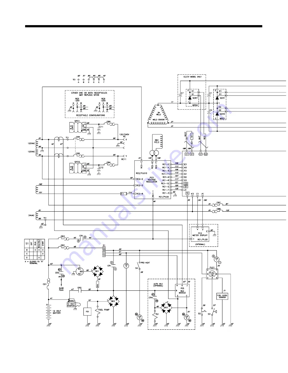
Page 52: ...OM 4422 Page 48 SECTION 9 ELECTRICAL DIAGRAMS Figure 9 1 Circuit Diagram For Welding Generator ...
Page 53: ...OM 4422 Page 49 219 228 B ...
Page 54: ...r specifications section in this manual to find rated voltage and current Do not idle engine longer than necessary Piston rings seat faster if engine runs at weld power rpm and the welding generatoris kept loaded during run in 2 Engine Exhaust Pipe Wetstacking is unburned fuel and oil in the exhaust pipe and occurs during run in if the engine is run too long at light load or idle rpm If exhaust pi...
Page 55: ...onnect load bank to generator weld output terminals using proper size weld cables with correct connectors Observe correct polarity Start engine and run for several minutes Set load bank switches and then adjust generator A V control so load equals rated voltage and current of generator see nameplate rating label or the specifications section in this manual Check generator and load bank meters afte...
Page 56: ... with correct connec tors polarity is not important 4 Voltmeter 5 Clamp On Ammeter Connect voltmeter and ammeter as shown if not provided on generator Start engine and run for several minutes Set grid switches and then adjust generator A V control so load equals rated voltage and current of the generator see nameplate rat ing label or the specifications sec tion in this manual Check generator and ...
Page 57: ...Generator To Truck Or Trailer Frame S 0854 Always ground generator frame to vehicle frame to pre vent electric shock and static electricity hazards 1 Equipment Grounding Terminal On Front Panel 2 Grounding Cable Not Supplied 3 Metal Vehicle Frame Connect cable from equipment ground terminal to metal vehicle frame Use 10 AWG or larger insulated copper wire If unit does not have GFCI re ceptacles us...
Page 58: ...sistive Load Equipment with a motor is a non re sistive load and requires approxi mately six times more power while starting the motor than when running see Section 11 8 3 Rating Data Rating shows volts and amperes or watts required to run equipment VOLTS 115 4 5 60 AMPS Hz 1 2 3 3 EXAMPLE 1 If a drill uses 4 5 amperes at 115 volts calculate its running power requirementin watts 4 5 A x 115 V 520 ...
Page 59: ... Home Equipment Rating Starting Watts Running Watts Stock Tank De Icer 1000 1000 Grain Cleaner 1 4 HP 1650 650 Portable Conveyor 1 2 HP 3400 1000 Grain Elevator 3 4 HP 4400 1400 Milk Cooler 2900 1100 Milker Vacuum Pump 2 HP 10500 2800 FARM DUTY MOTORS 1 3 HP 1720 720 Std e g Conveyors 1 2 HP 2575 975 Feed Augers Air 3 4 HP 4500 1400 Compressors 1 HP 6100 1600 1 1 2 HP 8200 2200 2 HP 10550 2850 3 H...
Page 60: ...HP 6000 1500 1 1 2 HP 8200 2200 2 HP 10500 2800 Electric Chain Saw 1 1 2 HP 12 in 1100 1100 2 HP 14 in 1100 1100 Electric Trimmer Standard 9 in 350 350 Heavy Duty 12 in 500 500 Electric Cultivator 1 3 HP 2100 700 Elec Hedge Trimmer 18 in 400 400 Flood Lights HID 125 100 Metal Halide 313 250 Mercury 1000 Sodium 1400 Vapor 1250 1000 Submersible Pump 400 gph 600 200 Centrifugal Pump 900 gph 900 500 F...
Page 61: ...or Starting Requirements Motor Start Code G H J K L M N P KVA HP 6 3 7 1 8 0 9 0 10 0 11 2 12 5 14 0 EXAMPLE Calculate the starting amperage required for a 230 V 1 4 HP motor with a motor start code of M Starting the motor requires 12 2 amperes 11 2 x 1 4 x 1000 230 12 2 A kVA HP x HP x 1000 VOLTS STARTING AMPERAGE Volts 230 HP 1 4 Using Table Code M results in kVA HP 11 2 11 9 How Much Power Can ...
Page 62: ...if required by electrical code 4 Welding Generator Output Generator output voltage and wiring must be consistent with regular utility system volt age and wiring Connect generator with temporary or perma nent wiring suitable for the installation Turn off or unplug all equipment connected to generator before starting or stopping engine When starting or stopping the engine has low speed which causes ...
Page 63: ...0 15 40 4800 112 34 62 19 37 11 45 5400 100 30 62 19 50 6000 87 26 50 15 Conductor size is based on maximum 2 voltage drop Cord Lengths for 240 Volt Loads If unit does not have GFCI receptacles use GFCI protected extension cord Maximum Allowable Cord Length in ft m for Conductor Size AWG Current Amperes Load Watts 4 6 8 10 12 14 5 1200 700 213 450 137 225 84 200 61 7 1680 800 244 500 152 300 91 20...
Page 64: ...ilable unless listed Wirng harnesses are listed at the end of parts section 1 Fig 15 3 2 7 3 Fig 15 5 4 6 8 9 5 10 11 12 14 15 13 16 17 105 96 97 18 19 20 21 22 23 94 95 87 85 84 83 82 88 89 90 91 93 92 98 99 100 102 103 101 Fig 15 2 105 104 86 Figure 12 1 Main Assembly ...
Page 65: ...Page 61 803 683 B 56 75 77 76 78 79 80 81 74 Fig 15 4 73 72 71 70 69 68 67 53 54 55 56 58 57 60 59 62 61 63 66 65 64 34 35 36 37 38 39 30 41 42 46 47 48 49 43 50 51 52 45 44 43 31 32 33 30 29 28 27 26 25 24 40 ...
Page 66: ...1 212604 Baffle Air Lower Radiator 1 22 201528 Muffler Exhaust Engine 1 23 212605 Pipe Exhaust Blue Fuel 1 24 213470 Cover Top 1 049525 Nut 312 18 U nut Multi thread 15 25 189052 Grommet Plastic Neck Filler Fuel 1 26 190198 Cap Tank Screw on 3 500 In W Vent W Lanyard 8 1 27 176104 Label Warning Falling Equipment Can Cause Serious 1 28 201851 Cover Radiator Access 1 29 214604 Pipe Exhaust Elbow 1 3...
Page 67: ... 3013 1 68 217686 Belt Alternator 1 69 210792 Engine Cat Dsl Elec 3013c 1800 Series Includes 1 212600 Flywheel Cat 3013c 1 202166 Filter Oil Cat 150 4140 1 217695 Switch Coolant Temp N c 110c 1 217696 Switch Lubricating Oil Pressure N O 1 70 212613 Hose Radiator Upper Cat 3013 1 71 216811 Clip Nut Retaining 2 72 197613 Air Cleaner Intake 5 250 In Includes 1 197675 Dust Ejector Air Cleaner 1 197676...
Page 68: ...4 Tray Reactor Rectifier 1 213491 Insulator Capacitor Bank Applies To Reactor Redtifier Tray 1 213506 Bracket Hold Down Fuel Tank Not Shown 1 98 220953 Upright Front 1 99 200795 Label Warning General Precautionary CSA 1 100 220955 Panel Front Access 1 101 Figure 12 2 Front Panel Assembly 1 102 105370 Xfmr Current 1 103 216347 Label Rating Card Code 133 Provide Serial No When Ordering 1 104 HD1 168...
Page 69: ...Front w Components Figure 12 1 Item 101 Quantity 1 097926 Knob Pointer 2 375 Dia X 250 Id W Set Screwsplstc 1 2 072590 Lock Shaft Pot 375 32 X 250 Dia Shaft Tall 1 3 170391 Conn Circ Ms Protective Cap Size 20 Nylon 1 4 190323 Boot Circuit Breaker Clear Hex Nut 2 5 097922 Knob Pointer 875 Dia X 250 Id W Set Screwsplstc 1 6 Nameplate Control Order By Model Serial No 1 7 PC6 217008 Circuit Card Assy ...
Page 70: ...erial No 24 GFCI1 2 151981 Rcpt Str Dx Grd 2p3w 15 20a 125v 5 20r Gfi Order By Model Serial No 25 C11 C12 217054 Capacitor Cer Disc 0047 Uf 3000 Vdc W Terms 2 26 CB4 CB6 093996 Circuit Breaker Man Reset 1p 20a 250vac Frict 2 27 CB5 203026 Circuit Breaker Man Reset 2p 50a 240vac Screw 90 1 28 GRD 083030 Stud Brs 250 20 X 1 750 W Hex Collar 1 29 010915 Washer Flat 257idx0 640odx 031t Brs 4 30 601836...
Page 71: ...l Mtg 1 7 F1 085874 Fuse Mintr Cer Slo blo 10 Amp 250 Volt 1 8 R4 214863 Resistor Board 1 9 CR4 090104 Relay Encl 12vdc Spst 30a 15vdc 5pin Flange Mtg 1 10 CR3 197325 Relay Encl 12vdc Spst 70a 4pin Flange Mtg 1 11 SR3 035704 Rectifier Integ Bridge 40 Amp 800v 1 12 SR1 SR2 035704 Rectifier Integ Bridge 40 Amp 800v 2 13 PC5 214761 Module Pull To Idle 1 14 CB2 CB3 083432 Circuit Breaker Man Reset 1p ...
Page 72: ...192686 Screw M 8 1 25x 25 Hex Hd pln 8 8 Pld Din933 6 10 212641 Stud Stl 375 16 1 625x 19 000 4 11 STATOR 212470 Stator Generator 4 Pole 1 12 160943 Endbell 1 13 167788 Nut 375 16 56hex 34h Stl Pld Sem Cone Wshr 88d 4 14 218552 Brush Assembly 2 Pole Includes 1 15 047879 Bar Retaining Brushholder 2 Brushes 1 16 161306 Cap Brushholder 2 17 126984 Brush w Spring 2 18 005614 Holder Brush 2 19 125548 H...
Page 73: ... Module SCR 3 3 MOD4 5 6 218292 Kit Module SCR 3 4 212602 Bus Bar Rectifier 1 5 212639 Bus Bar Rectifier 3 6 212601 Insulator Rectifier 1 7 TH1 213930 Thermistor Ntc 30k Ohm 25 Deg C 8 5in Lead 1 8 C1 6 215611 Capacitor Assy 3 9 C7 8 9 048420 Capacitor Cer Disc 01 Uf 1000 Vdc W Terms 3 10 217085 Bus Bar Rectifier 1 181853 Insulator Screw For Mounting Rectifier 4 To maintain the factory original pe...
Page 74: ...n Pack 4p 1row Female 1 For S1 211293 Conn Pack Terminal Position Assurance Lock 1 129524 Term Frict 250x032 Uninsul Male 130 Stud Mtg 3pr 2 217002 Harness Weld Control Includes 1 PLG2 150316 Conn Rect Univ 039 6p S 3row Plug Cable Lkg 1 PLG9 214951 Conn Rect Univ 039 6p S 3row Plug Cable Lkg Seal 1 214933 Seal Wire Univ 039 3 214934 Seal Plug Univ 039 3 PLG8 147992 Conn Rect Univ 039 10p S 2row P...
Page 75: ...and Blankets APT SAF Model Plasma Cutting Torches Remote Controls Accessory Kits Replacement Parts No labor Spoolmate Spoolguns Canvas Covers Miller s True Blue Limited Warranty shall not apply to 1 Consumable components such as contact tips cutting nozzles contactors brushes slip rings relays or parts that fail due to normal wear Exception brushes slip rings and relays are covered on Bobcat Trail...
Page 76: ... complete and retain with your personal records Always provide Model Name and Serial Style Number Call 1 800 4 A Miller or see our website at www MillerWelds com to locate a DISTRIBUTOR or SERVICE AGENCY near you Welding Supplies and Consumables Options and Accessories Personal Safety Equipment Service and Repair Replacement Parts Training Schools Videos Books Technical Manuals Servicing Informati...