background image

OM-248965 Page 16

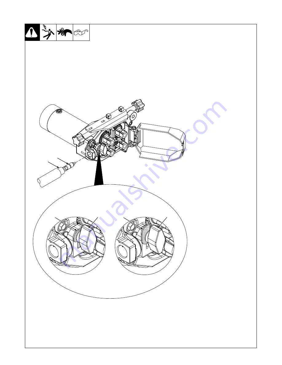
5-5. Installing Welding Gun

Ref. 249 398-A

1

Gun Locking Tab

2

Power Clamp Knob

3

Gun Connection End

4

Power Pin Groove

Installing gun with Accu-Mate

connection

Loosen power clamp knob to allow

power pin of gun to clear the gun

locking tab.
Push power pin into power clamp

as far as possible to align the

groove in the power pin of the gun

with the gun locking tab.
Secure gun by tightening power

clamp knob.

Installing gun without Accu-

Mate


connection

When using a gun without the

groove in the power pin, loosen

power clamp knob and rotate gun

locking tab 180 degrees. This pre-

vents the locking tab from extend-

ing into the power pin gun connec-

tion.
Push power pin into power clamp

as far as possible.
Secure gun by tightening power

clamp knob.

4

Installing gun with

Accu-Mate connection

Installing gun without

Accu-Mate connection

3

2

2

1

1

Summary of Contents for Axcess E Dual

Page 1: ...l Wire Feeder Processes Description MIG GMAW Welding Wire Feeder OM 248965G 2016 05 File Advanced Manufacturing Systems Visit our website at www MillerWelds com ams R Flux Cored FCAW Welding Gas And S...

Page 2: ...ntinue the tradition They re just as committed to providing equipment and service that meets the high standards of quality and value established in 1929 This Owner s Manual is designed to help you get...

Page 3: ...cifications 13 SECTION 5 INSTALLATION 13 5 1 Selecting A Location 13 5 2 Connection Diagram 14 5 3 Rear Panel Connections And Rotating Drive Assembly 15 5 4 9 Pin Network Receptacle Information 15 5 5...

Page 4: ......

Page 5: ...neeling or lying or when there is a high risk of unavoid able or accidental contact with the workpiece or ground For these conditions use the following equipment in order presented 1 a semiautomaticDC...

Page 6: ...ared according to AWS F4 1 and AWS A6 0 see Safety Standards D Do not weld where the atmosphere can contain flammable dust gas or liquid vapors such as gasoline D Connect work cable to the work as clo...

Page 7: ...S can injure D Keep away from moving parts such as fans D Keep all doors panels covers and guards closed and securely in place D Have only qualified persons remove doors panels covers or guards for ma...

Page 8: ...PA Standard 51B from National Fire Protection Association Quincy MA 02269 phone 1 800 344 3555 website www nfpa org OSHA Occupational Safety and Health Standards for General Indus try Title 29 Code of...

Page 9: ...s dans un environnement humideou si l on porte des v tements mouill s sur des structures m talliquestelles que sols grilles ou chafaudages en position coinc e comme assise genoux ou couch e ou s il y...

Page 10: ...br lures Le contact accidentel de l lectrode avec des objets m talliques peut provoquer des tincelles une explosion un sur chauffement ou un incendie Avant de commencer le soudage v rifier et s assur...

Page 11: ...areil D Tenir l quipement c bles et cordons distance des v hicules mobiles lors de toute op ration en hauteur D Suivre les consignes du Manuel des applications pour l quation de levage NIOSH r vis e P...

Page 12: ...ational Electrical Code NFPA Standard 70 from National Fire Protec tion Association Quincy MA 02269 phone 1 800 344 3555 website www nfpa org and www sparky org Safe Handling of Compressed Gases in Cy...

Page 13: ...OM 248965 Page 9 Notes...

Page 14: ...ation Safe37 2012 05 Wear dry insulating gloves Do not touch electrode with bare hand Do not wear wet or damaged gloves Safe2 2012 05 Protect yourself from electric shock by insulating yourself from w...

Page 15: ...welding voltage during operation keep hands and metal objects away Safe33 2012 05 Wear hat and safety glasses Use ear protection and button shirt collar Use welding helmet with correct shade of filte...

Page 16: ...urge By Gas Fast Constant Current Circuit Breaker Constant Voltage Slow Trigger Hold Off Trigger Hold On I2 Rated Welding Current Increase Read Instructions U1 Primary Voltage U2 Conventional Load Vol...

Page 17: ...peres 100 Duty Cycle Length 27 in 686 mm Width 12 1 2 in 318 mm Height 14 1 2 in 368 mm 87 lb 39 5 kg 4 3 Environmental Specifications IP Rating IP2X This equipment is designed for indoor use and is n...

Page 18: ...s Cylinder 4 Gas Hose 5 Network Feeder Cable 6 Negative Weld Cable 7 Workpiece 8 Voltage Sensing Lead Recommendedfor Accu pulse and RMD optional Positive voltage sensing lead is contained in the motor...

Page 19: ...per Cable 6 Weld Cable 7 Drive Assembly 8 Drive Assembly Rotation Knob Left And Right 9 Rating Label Location To rotate the drive assembly loosen drive assembly rotation knob rotate drive assembly and...

Page 20: ...in the power pin of the gun with the gun locking tab Secure gun by tightening power clamp knob Installing gun without Accu Mate connection When using a gun without the groove in the power pin loosen p...

Page 21: ...soft wire or small diameter stainless steel wire reduce drive roll pressure on the rear roll to half that of the front rolls To adjust drive roll pressure hold nozzle about 2 in 51 mm from nonconducti...

Page 22: ...hes before the power source is fully operational Program Process Wire Type Gas Type Trigger Control Adjust Volts Time WFS Amps Process Set Up Feeder Set Up Trigger Hold 2 1 Arc Adjust Arc Ctl Sequence...

Page 23: ...ual Schedule Switch Option 1 Maint 2P Maintained Contact 2 Pole Switch DSS 9M Part 041793 2 Adapter Part 157364 needed for Bernard and Tregaskiss dual schedule torches 1 1 1 2 2 3 A 4 B DSS 9M 1 1 2 2...

Page 24: ...Crater Allows setting of voltage arc adjust wire feed rate and time value for arc ends DS Dual Schedule Dual Schedule allows selecting a program within a pair of programs by means of a dual schedule s...

Page 25: ...Trigger Program Select TPS allows the operator to select weld programs by using the gun trigger In TPS mode momentarily pressing the gun trigger allows the operator to cycle through preselected weld p...

Page 26: ...er display Af ter 3 seconds the weld output turns off and the wire will feed at 60 ipm for the next 3 sec onds and then ramps up to 700 ipm until trig ger is released or 30 seconds elapses If the gun...

Page 27: ...ee Section 6 7 See Section 6 8 See Section 6 11 See Section 6 10 See Section 6 9 See Section 6 6 Program Process Wire Type Gas Type Trigger Control Adjust Volts Time WFS Amps Process Set Up Feeder Set...

Page 28: ...show actual voltage for approximately 3 seconds after welding stops before returning to preset value 2 Upper Display Push Button Press the button to illuminate the LED and allow changing information i...

Page 29: ...can be adjusted using the Adjust knob 6 Lower Display Push Button 7 Lower Display Push Button LED Pressing the button illuminates the LED and selects either WFS or Arc Ctl value for changing using the...

Page 30: ...l illuminate and the upper display will show the different trig ger control selections Use the Adjust knob to cycle through the trigger control methods as follows DS IGNR TH TDS TPS and 4T see Section...

Page 31: ...rth time will keep Wire Type LED lit and the upper display will show wire size The upper display push button will be flashing indicating that turning the Adjust knob will select wire sizes available f...

Page 32: ...rgon 5 CO2 95 Argon 5 O2 CO2 C10 C15 C25 C5 OX5 Stainless Steel SS 308 309 312 316 98 Argon 2 O2 81Ar 18HE 1CO2 Accu pulse 90HE 7 1 2Ar 2 1 2CO2 MIG RMD OX2 Tri Gas Tri Gas Cored Tubular Wire MCOR 71...

Page 33: ...le display shows a model 450 AXCS 450 Trigger Control Program Process Wire Type Gas Type Process Set up Volts Time Arc Adjust WFS Amps Arc Ctl Sequence Trigger Hold Adjust Feeder Set Up After entering...

Page 34: ...Adjust Feeder Set Up RST NO LED Program 1 Pulse 035 Mild Steel 90 Argon 10 CO2 Program 2 MIG 035 Mild Steel 75 Argon 25 CO2 Program 3 Accu pulse 035 Mild Steel 90 Argon 10 CO2 Program 4 Pulse 045 Mild...

Page 35: ...SW Rotate Adjust knob until Software Revision SW REV appears on the display Rotate Adjust knob to scroll through the software revision for each circuit board Trigger Control Program Process Wire Type...

Page 36: ...just Feeder Set Up ENBL CAC Rotate Adjust knob until Carbon Arc Cutting Enable CAC ENBL appears on the display Rotate Adjust knob to select NO or YES Trigger Control Program Process Wire Type Gas Type...

Page 37: ...il Voltage Feedback VOLT FDBK appears on the display Rotate Adjust knob to select STUD or volt sense lead VSNS Trigger Control Program Process Wire Type Gas Type Process Set up Volts Time Arc Adjust W...

Page 38: ...ust Feeder Set Up BANK LOAD Rotate Adjust knob until Load Bank LOAD BANK appears on the display Rotate Adjust knob to select OFF or ON Trigger Control Program Process Wire Type Gas Type Process Set up...

Page 39: ...as Type Process Set up Volts Time Arc Adjust WFS Amps Arc Ctl Sequence Trigger Hold Adjust Feeder Set Up RST OFF LED Unit goes back to its standby status RST ON Trigger Control Program Process Wire Ty...

Page 40: ...skipped Maximum IPM may actually be lower depending on wire size and gas combination Additional sequence set up changes can be made using the HTML pages Refer to the HTML pages for additional informa...

Page 41: ...aining Maintain more often during severe conditions n Check Z Change Clean l Replace To be done by Factory Authorized Service Agent Reference Every 3 Months l Unreadable Labels Weld Terminals l Damage...

Page 42: ...I Unknown Error ERR UNKN Section 8 2 J Motor Communications Error MOTR COMM Section 8 2 K Over Average Current OVER AVE Section 8 2 L Over Current OVER CRNT Section 8 2 M Release Trigger REL TRIG Sec...

Page 43: ...software C No Coolant Flow Error ERR COOL Indicates no coolant flow in water flow switch option The error may be reset by reestablishing coolant flow to the gun and then pressing the Jog Purge button...

Page 44: ...r Up Cnt that generated by the boost section of the inverter control board When either of these signals is active RC6 12 is pulled low this is the not ready line out of the inverter control board Shut...

Page 45: ...chassis lifting eye bolts or weld secondary common Measure impedance between chassis and both weld secondary commons Measure the impedance across motor isolation barrier on motor housing All measureme...

Page 46: ...l A change to a different resistor eliminated this situation and the problem is no longer an issue S A shorted output diode will cause an over current error and no weld output will be available N Rele...

Page 47: ...ists con tact nearest Factory Authorized Service gent V Low Wire Feed Speed Error LOW WFS Indicates actual wire feed speed is lower than wire feed speed command Check for obstructions in the wire feed...

Page 48: ...PWR Request to cycle power from the welding power source Turn unit power off and back on again AD PCM Bus Communication Indicates no error message on the displays PCM board PC4 DeviceNet has gone off...

Page 49: ...n or replace dirty or worn drive roll Incorrect size or worn wire guides Replace contact tip or liner See gun Owner s Manual Remove weld spatter or foreign matter from around nozzle opening Have Facto...

Page 50: ...ion must be entered on the web pages for the unit to function properly The user will be prompted for power source serial number model and type Semi Auto AROI AUTO etc as shown in Figure 8 2 Figure 8 2...

Page 51: ...mpatible the ERR S W will appear on the display see Figure 8 3 Compatible software can be downloaded from www MillerWelds com ERR S W Trigger Control Program Process Wire Type Gas Type Process Set up...

Page 52: ...es Port A on the power source is factory set to 169 254 0 2 as a static IP address Connect a PC to Port A and enter 169 254 0 2 in the web browser to access the web pages AXCESS E Login Page ITW Weldi...

Page 53: ...System Settings Machine Lifetime Report Short Term Weld Data Weld Communications Errors Time Settings Ethernet Settings More Subselect and type additional text here Welder Information Subselect and t...

Page 54: ...OM 248965 Page 50 SECTION 10 ELECTRICAL DIAGRAM Figure 10 1 Circuit Diagram...

Page 55: ...OM 248965 Page 51 218 564 F...

Page 56: ...5 Page 52 SECTION 11 PARTS LIST 804 023 A Hardware is common and not available unless listed 12 19 2 1 3 17 18 7 16 8 11 9 10 6 20 15 11 10 14 5 22 4 Figure 11 3 21 Figure 11 2 9 13 Figure 11 1 Main A...

Page 57: ...Spool 1 13 071730 Tubing Stl 875 OD x 12 Ga Wall x 2 500 1 14 135205 Nut 625 11 94 Hex 77h Stl Pld Elastic Stop Nut 1 15 141411 Support Spool 1 16 208339 Knob w Extension LH Clamp 1 16 208338 Knob w E...

Page 58: ...elay 1 8 010494 Bushing Snap In Nyl 1 375 ID x 1 750 Mtg Hole 2 220314 Filter Assy Sense Lead Includes 2 9 038855 Block Term 20 Amp 2 Pole Screw Term 2 10 216696 Capacitor w Terminals 027uf 2 11 22438...

Page 59: ...Panel Front 1 22 248964 Nameplate Lower 1 23 S2 200295 Switch Rocker SPDT 15A 12V On Off On 2 24 201641 Switch Rocker SPDT 15A 12V On Off On 2 25 179851 Knob Pointer 1 670 Dia X 250 ID Push On W Sprin...

Page 60: ...Pin Hinge 1 9 M1 213005 Motor Gear 1 203631 Pressure Arm Includes 1 10 182415 Pin Cotter Hair 1 11 203640 Knob w Extension Short Pressure Arm 1 12 133739 Washer Flat Buna 375 ID x 625 OD x 062thk 2 1...

Page 61: ...wer Pin 2 29 242261 Lock Power Pin 2 30 231232 Washer Flat 344 ID x 0 688 OD x 065t Stl Pld Ansi 312 1 31 151437 Knob Plstc T 1 125 Lg x 312 18 x 1 500 1 32 185624 Screw 010 32 x O 50 Hexwhd 40d Stl P...

Page 62: ...1 6 mm 151029 151039 151055 151072 243235 068 072 in 1 8 mm 151056 5 64 in 2 0 mm 151040 151057 151073 3 32 in 2 4 mm 151041 151058 151074 7 64 in 2 8 mm 151042 151059 151075 1 8 in 3 2 mm 151043 1510...

Page 63: ...ns and Subarc SAW Torches Remote Controls and RFCS RJ45 Replacement Parts No labor Roughneck Guns Spoolmate Spoolguns Miller s True Blue Limited Warranty shall not apply to 1 Consumable components suc...

Page 64: ...your personal records Always provide Model Name and Serial Style Number Contact a DISTRIBUTOR or SERVICE AGENCY near you Welding Supplies and Consumables Options and Accessories Personal Safety Equip...

Reviews: