background image

OM-224 043 Page 3

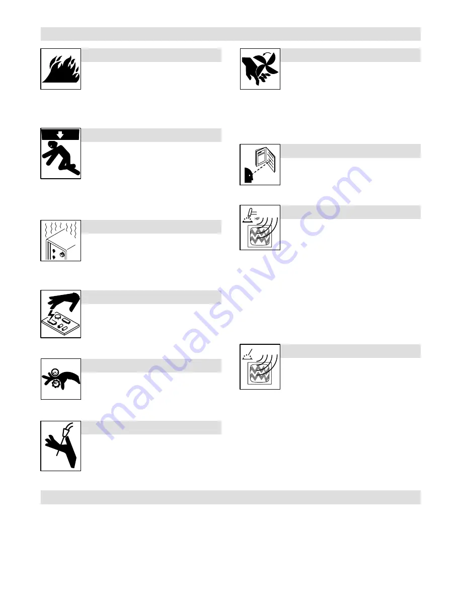
1-3. Additional Symbols For Installation, Operation, And Maintenance

FIRE OR EXPLOSION hazard.

D

Do not install or place unit on, over, or near

combustible surfaces.

D

Do not install unit near flammables.

D

Do not overload building wiring 

 be sure power supply system is

properly sized, rated, and protected to handle this unit.

FALLING UNIT can cause injury.

D

Use lifting eye to lift unit only, NOT running

gear, gas cylinders, or any other accessories.

D

Use equipment of adequate capacity to lift and

support unit.

D

If using lift forks to move unit, be sure forks are

long enough to extend beyond opposite side of

unit.

OVERUSE can cause OVERHEATING

D

Allow cooling period; follow rated duty cycle.

D

Reduce current or reduce duty cycle before

starting to weld again.

D

Do not block or filter airflow to unit.

STATIC (ESD) can damage PC  boards.

D

Put on grounded wrist strap BEFORE handling

boards or parts.

D

Use proper static-proof bags and boxes to

store, move, or ship PC boards.

MOVING PARTS can cause injury.

D

Keep away from moving parts.

D

Keep away from pinch points such as drive

rolls.

WELDING WIRE can cause injury.

D

Do not press gun trigger until instructed to do

so.

D

Do not point gun toward any part of the body,

other people, or any metal when threading

welding wire.

MOVING PARTS can cause injury.

D

Keep away from moving parts such as fans.

D

Keep all doors, panels, covers, and guards

closed and securely in place.

D

Have only qualified persons remove doors,

panels, covers, or guards for maintenance as

necessary.

D

Reinstall doors, panels, covers, or guards

when maintenance is finished and before re-

connecting input power.

READ INSTRUCTIONS.

D

Read Owner’s Manual before using or servic-

ing unit.

D

Use only genuine Miller/Hobart replacement

parts.

H.F. RADIATION can cause interference.

D

High-frequency (H.F.) can interfere with radio

navigation, safety services, computers, and

communications equipment.

D

Have only qualified persons familiar with

electronic equipment perform this installation.

D

The user is responsible for having a qualified electrician prompt-

ly correct any interference problem resulting from the installa-

tion.

D

If notified by the FCC about interference, stop using the

equipment at once.

D

Have the installation regularly checked and maintained.

D

Keep high-frequency source doors and panels tightly shut, keep

spark gaps at correct setting, and use grounding and shielding to

minimize the possibility of interference.

ARC WELDING can cause interference.

D

Electromagnetic energy can interfere with

sensitive electronic equipment such as

computers and computer-driven equipment

such as robots.

D

Be sure all equipment in the welding area is

electromagnetically compatible.

D

To reduce possible interference, keep weld cables as short as

possible, close together, and down low, such as on the floor.

D

Locate welding operation  100 meters from any sensitive elec-

tronic equipment.

D

Be sure this welding machine is installed and grounded

according to this manual.

D

If interference still occurs, the user must take extra measures

such as moving the welding machine, using shielded cables,

using line filters, or shielding the work area.

1-4. California Proposition 65 Warnings

Y

Welding or cutting equipment produces fumes or gases which

contain chemicals known to the State of California to cause

birth defects and, in some cases, cancer. (California Health &

Safety Code Section 25249.5 et seq.)

Y

Battery posts, terminals and related accessories contain lead

and lead compounds, chemicals known to the State of

California to cause cancer and birth defects or other

reproductive harm. Wash hands after handling.

For Gasoline Engines:

Y

Engine exhaust contains chemicals known to the State of

California to cause cancer, birth defects, or other reproductive

harm.

For Diesel Engines:

Y

Diesel engine exhaust and some of its constituents are known

to the State of California to cause cancer, birth defects, and

other reproductive harm.

Summary of Contents for XMS 4000

Page 1: ...Processes Multiprocess Welding OM 224 043B 2006 07 Description Arc Welding Power Source XMS 4000 400 Volts R...

Page 2: ...ucts Please take time to read the Safety precautions They will help you protect yourself against potential hazards on the worksite We ve made installation and operation quick and easy With Miller you...

Page 3: ...put Power 14 SECTION 4 OPERATION 15 4 1 Front Panel Controls 15 4 2 Switching On the Unit and Recalling Factory Parameters 16 4 3 Welding Process Selection 16 4 4 Wire Type Selection in Synergic MIG o...

Page 4: ...4000 conforms to the following Directives and Standards Directives Electromagnetic compatibility Directives 89 336 EEC 92 31 EEC Low Voltage Directive 73 23 EEC Machinery Directives 89 392 EEC and th...

Page 5: ...0 147 see Safety Standards D Properly install and ground this equipment according to its Owner s Manual and national state and local codes D Always verify the supply ground check and be sure that inpu...

Page 6: ...mbustibles such as a butane lighter or matches from your person before doing any welding D Follow requirements in OSHA 1910 252 a 2 iv and NFPA 51B for hot work and have a fire watcher and extinguishe...

Page 7: ...s computers and communicationsequipment D Have only qualified persons familiar with electronic equipment perform this installation D The user is responsible for having a qualified electrician prompt l...

Page 8: ...Occupational Safety and Health Standards for General Indus try Title 29 Code of Federal Regulations CFR Part 1910 Subpart Q and Part 1926 Subpart J from U S Government Printing Office Super intendent...

Page 9: ...ding sparks can cause explosion or fire 3 1 Keep flammables away from welding Do not weld near flammables 3 2 Welding sparks can cause fires Have a fire extinguisher nearby and have a watchperson read...

Page 10: ...s of parts can cause injury Always wear a face shield when servicing unit 8 Always wear long sleeves and button your collar when servicing unit 9 After taking proper precautions as shown connect power...

Page 11: ...n filter and check condition of hoses 6 Read Owner s Manual 7 Use coolant suggested by manufacturer B 050024004 1 Warning Watch Out There are possible hazards as shown by the symbols 2 Falling unit ca...

Page 12: ...rc Welding Three Phase Static Frequency Con verter Transformer Rectifier Gas Metal Arc Welding GMAW Shielded Metal Arc Welding SMAW Recycle or dispose of used coolant in an environmentally safe way U1...

Page 13: ...0 09 11 5 0 04 While idling 6 Minutes Welding 4 Minutes Resting 3 2 Duty Cycle And Overheating Duty Cycle is percentage of 10 min utes that unit can weld at rated load without overheating If unit ove...

Page 14: ...talling Turntable for Wire Feeder on Power Source Optional Y Turn off welding power source and disconnect input power before proceeding Remove wire spool 1 Turntable 2 Screw Remove the 4 screws and th...

Page 15: ...eds 3 Line Disconnect Device Locate unit near correct input power supply Y Special installation may be required where gasoline or volatile liquids are present see NEC Article 511 or CEC Section 20 102...

Page 16: ...acle TIG STICK Negative receptacle MIG 150 30 30 35 50 60 70 95 95 p TIG STICK p MIG 200 30 35 50 60 70 95 120 120 250 35 50 60 70 95 120 2 70 2 70 300 50 60 70 95 120 2 70 2 95 2 95 350 60 70 95 120...

Page 17: ...Unscrew cap from tank Use table to select proper coolant and fill tank until coolant appears in upper half of indicator Check coolant level after attaching torch coolant hoses and running cooler Be su...

Page 18: ...s are UL class RK5 3 Normal Operating general purpose no intentional delay fuses are UL class K5 up to and including 60 amp and UL class H 65 amp and above 4 Conductor data in this section specifies c...

Page 19: ...se lected welding process During welding it shows measured welding current 12 E1 Encoder Control 1 Use control to change values and parame ters that appear on D1 13 E2 Encoder Control 2 Use control t...

Page 20: ...lt is 0 0 T range is 5 0 T to 5 0 T D2 value is wire feed speed from minimum to maximum value according to welding curve selection When L2 is flashing material transfer in the arc is by large droplets...

Page 21: ...ng AlMg AlMg5 or AlSi AlSi5 Special allows selecting cored wire or spe cial wire abbreviations for the different wire types will appear on D1 and D2 Be aware that the wire type selection is retained i...

Page 22: ...enabling and dis abling STICK welding In TIG welding pressing P6 will change the trigger mode but D1 and D2 will not change values In STICK welding pressing P6 will enable welding L20 ON D1 shows open...

Page 23: ...elected process parameter values Setup allows viewing and changing default parametervalues for all welding processes for the desired weld characteristics D1 shows the welding parameter D2 shows the pa...

Page 24: ...tacle on the wire feeder see Wire Feeder manual Turn unit On Allow time for unit to complete its start up cycle Set MIG welding process using P3 push button 4 11 Selecting Manual MIG Welding Set Manua...

Page 25: ...ng Setting D1 value is default voltage setting range is definedby wire type wire diameter and gas type selection D2 value is the default current setting range is defined by wire type wire diame ter an...

Page 26: ...ger mode using P6 push button See wire feeder manual for all the remain ing Synergic MIG settings Setting Cooler Status see Section 4 11 Setting Synergic Double Pulsed MIG Welding Some metals weld bet...

Page 27: ...ly in MENU FULL To set initial and final amperage proceed as follows Press P2 to enter SET UP menu Select MENU FULL on D1 and D2 see Section 4 9 Use E1 to change D1 to IN A D2 value is default setting...

Page 28: ...afety precautions according to Section 1 Prepare unit according to Section 3 Connect electrode holder to the Positive power connector 2 Connect work clamp cable to the Work connector 3 If a remote con...

Page 29: ...e conditions 3 Months Replace Damaged Or Unreadable Labels Replace Cracked Torch Body Repair Or Replace Cracked Cables Repair Or Replace Cracked Cables And Cords Clean And Tighten Weld Connections 6 M...

Page 30: ...run until inter nal temperature drops within operational range Help 6 Indicates input voltage is too low and unit has automaticallyshut down Operation will con tinue when voltage is within an acceptab...

Page 31: ...roper weld output Use proper size and type of weld cable see Section 3 6 Clean and tighten all weld connections Coolant system not working HELP 15 is displayed Check and secure coolant hose connectors...

Page 32: ...OM 224 043 Page 28 Notes...

Page 33: ...OM 224 043 Page 29 SECTION 6 ELECTRICAL DIAGRAM May 9 2005...

Page 34: ...OM 224 043 Page 30 SECTION 7 PARTS LIST Hardware is common and not available unless listed May 11 2005 Figure 7 1 Unit Outer Assembly...

Page 35: ...dia 2 11 156012013 Wheels pivot 1 12 V16122151 Expanded plate dx 1 13 000207233 Label warning 1 14 056054074 Wheels pivoting 100 mm dia 2 15 V56142156 Label logo 1 16 000208154 Panel front plastic 1 1...

Page 36: ...OM 224 043 Page 32 Hardware is common and not available unless listed May 11 2005 Figure 7 2 Unit Main Assembly...

Page 37: ...fan 2 46 V16006153 Base 1 47 V57094063 Receptacle kit 7 pin 1 48 V16118147 Panel front 1 49 000128756 Switch 40 A 600 VAC 1 50 V56014149 Board protection 1 51 RL1 000006393 Relay 24 VAC 1 52 CB1 0001...

Page 38: ...Notes...

Page 39: ...shall not apply to 1 Consumable components such as contact tips cutting nozzles contactors brushes slip rings relays or parts that fail due to normal wear 2 Items furnished by Miller but manufactured...

Page 40: ...stal Code Please complete and retain with your personal records Owner s Record Always provide Model Name and Serial Style Number Contact a DISTRIBUTOR or SERVICE AGENCY near you Welding Supplies and C...

Reviews: