OM-817 Page 5
6.
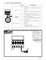
Remote 14 Receptacles Information
A
J
B
K
I
C L N
H
D M
G
E
F
Socket*
Socket Information
Remote Contactor
A
24 volts AC.
B
Contact closure to A completes 24 volts AC contactor control
circuit.
I
115 volts AC.
J
Contact closure to I completes 115 volts AC contactor control
circuit.
G
Circuit common for 24 and 115 volts AC circuits.
Remote
Amperage/Voltage
Control
C
Command reference; +10 volts DC output to remote control.
D
Remote control circuit common.
E
0 to +10 volts DC input command signal from remote control.
K
Chassis common.
Remote Output Control
H
Voltage feedback; +1 volt DC per 10 output (arc) volts.
L
Not used.
M
Mode select.
N
Remote inductance control.
F
Current feedback; +1 volt DC per 100 amperes.
7.
Welding Power Source Remote 14 Receptacle And 115 Volt Receptacle Connections
ST-800 201-B / Ref. 800 101
1
Remote Control Plug
Connect to the welding power
source Remote 14 receptacle.
2
115 Volt Receptacle
Connect the 115 volt plug from
high frequency unit to this recep-
tacle.
3
Circuit Breaker CB1–Protects
unit from overload.
Y
Pin K in welding power
source must be grounded.
See welding power source
circuit diagram to be sure.
1
2
3


