


www.milleredge.com [email protected] 800-220-3343
5/5
6. ERASING THE RBAND RECEIVER
If you encounter intermittent performance or you have any other programming issues, erase the RBand Receiver and reprogram
the Transmitters. The Receiver will search for a clear RF channel.
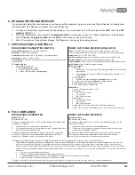
1. To erase all Transmitters programmed into the Receiver, use a screwdriver to short the two pins marked
MR next to the DIP
switches [IMAGE 2].
2. While shorting the pins, press and hold the
program button; you will hear a series of 10 beeps followed by a rapid chirping
sound. Release the
program button and the MR pin short when your hear the chirping
3. Wait ~10 seconds and you will hear 2 beeps. The Receiver is now ready to be reprogrammed.
7. SPECIFICATIONS & CONTROLS
RBAND EDGE TRANSMITTER (RB-TX10)
Transmitter Frequency: 916 MHz, FSK modulation
Mounting: 4 corner screws (provided)
Power Source: Batteries: 2 AA, 3.6V lithium, 2 year life expectancy
Dimensions: 1.80”L x 4.78”W x 1.75”H
Program Button: Momentary push button is used to associate the Transmitter
to the Receiver
TX Indicator Lights:
•
Green LED: Normally off
•
Press
program button for status:
1.
Green LED
off: Good edge
2.
Green LED
on: Active or damaged edge
RBAND GATE EDGE RECEIVER (RB-G-RX10)
Power: 12-24 VAC/DC nominal (11-30 V max); 100 mA max current draw.
Power may be supplied from the operator or alternatively from an external supply.
Dimensions: 4.12”L x 3.65”W x 1.65”H
Cable Connections: Screw clamp type terminal blocks for 18-26 AWG wire
External Antenna: Monopole antenna supplied (gain: 5dBi +/-2dB)
Program Button: Used to associate a Transmitter with the desired receiver channel
Check Button: Used to determine signal strength
RX Indicator Lights:
•
Check LED:
1.
Blinks every ~5 seconds to indicate working properly if both channels are
programmed
2.
After
check button is pressed, blinks to indicate signal strength; 4 or 5
blinks is ideal
•
R1 and R2 LEDs:
1.
Off when the associated edge is learned and has no faults
2.
On solid: No Transmitters learned or edge activated
•
R3 LED:
On when low battery relay is active
•
A TEST LED:
On when in test mode
Connections:
•
Power (2): Positive and ground, or AC
•
Relay Output 1:
1.
CS1: Normally Closed
2.
C1: Common
3.
BS1: 10K termination
•
Relay Output 2:
1.
CS2: Normally Closed
2.
C2: Common
3.
BS2: 10K termination
•
Relay Output 3 (2): Relay closes when low battery is detected
•
A TEST (2): Connect to switched DC power (+ and Com) for N.C. monitoring
8. FCC COMPLIANCE
RBAND EDGE TRANSMITTER
Model: RB-TX10
FCC ID: U5Z-RB-TX10
This device complies with Part 15 of the FCC rules. Operation is subject to the
following two conditions:
1.
This device may not cause harmful interference and
2.
This device must accept any interference received, including interference
that may cause undesired operation.
This device complies with FCC radiation exposure limits for an uncontrolled
environment. This device shall be installed and operated with a minimum
distance of 0.4” between users or bystanders and the device.
RBAND GATE EDGE RECEIVER
Model: RB-G-RX10
FCC ID: U5Z-RB-G-RX10
This device complies with Part 15 of the FCC rules. Operation is subject to the
following two conditions:
1.
This device may not cause harmful interference and
2.
This device must accept any interference received, including interference
that may cause undesired operation.
This device complies with FCC radiation exposure limits for an uncontrolled
environment. This device shall be installed and operated with a minimum
distance of 0.8” between users or bystanders and the device.
This equipment has been tested and found to comply with the limits for a Class B digital device, pursuant to Part 15 of the FCC Rules:
These limits are designed to provide reasonable protection against harmful interference in a residential installation. This equipment generates, uses and can
radiate radio frequency energy and, if not installed and used in accordance with the instructions, may cause harmful interference to radio communications.
However, there is no guarantee that interference will not occur in a particular installation. If this equipment does cause harmful interference to radio or television
reception, which may be determined by turning the equipment off and on, the user is encouraged to try to correct the interference by one or more of the following
measures:
1.
Re-orient or relocate the receiver antenna
2.
Increase the separation between the equipment and the receiver
3.
Connect the equipment into an outlet on a circuit different from that to which the receiver is connected
4.
Consult the dealer or an experienced radio/TV technician for help
Changes or modifications not expressly approved by the party responsible for compliance could void the user’s authority to operate the equipment.


