Mikroe EasyPIC PRO v8 User Manual Download Page 24

P A G E  24

E a s y P I C  P R O  v 8  M a n u a l

C O M M U N I C A T I O N
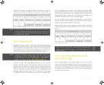
Communication

Communication connectors allow the development board to be connected 
with many different devices that use high-layer communication protocols 
such as Ethernet, USB, etc. Also, there is a USB-UART converter, offering 
simplified communication with the personal computer over the emulated 
serial interface. Each of these connectors will be described in more details, in 
the following sections of the manual.
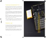
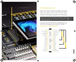
USB-UART 


UART (Universal Asynchronous Receiver/Transmitter) interface is one of 
the most common interfaces for data exchange between the MCU and 
other external devices. EasyPIC PRO v8 development board offers the UART 
connectivity over the USB-C connector 

(1)

 by utilizing the FT230XQ, a popular 

USB-UART bridge IC, produced by FTDI Chip. This IC contains the complete 
USB stack necessary for the interface bridging between the UART peripheral 
of the MCU and the USB interface of the PC. FT230XQ drivers are available 
for download from the EasyPIC PRO v8 product web page, as well as from the 
official FTDI drivers download web page. 

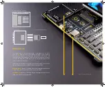
To enable data exchange via the USB-UART connector, the MCU UART 
peripheral lines must be connected to the corresponding pins of the FT230XQ 
IC. This can be done using the two-pole DIP switch, labeled as USB/UART 
(SW2 on the schematic). Only two switch positions are used for the UART 
setup:

SW2.1

  ON  (up):

 connects the UART TX pin from the MCU to the FT230XQ IC;  


OFF (down):

 disconnects the UART TX pin from the FT230XQ IC

SW2.2 

ON (up):

 connects the UART RX pin from the MCU to the FT230XQ IC;


OFF (down):

 disconnects the UART RX pin from the FT230XQ IC
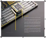
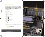
USB

USB (Universal Serial Bus) is a very popular industry standard that defines 
cables, connectors, and protocols used for communication and power supply 
between devices. USB-C connector 

(1)

 is the latest version of the USB 

connector, developed by the USB Implementation Forum (USB-IF). Due to 
its many advantages including symmetrical pinout, higher current capacity, 
and support for faster data rates, it offers a significant improvement over the 
previous versions. This allows MCU devices equipped with the USB peripheral 
to connect to an external USB HOST (such as a PC, Laptop, etc.), allowing the 
development of USB-based applications. The connection to the USB HOST is 
indicated by a yellow LED labeled as VBUS, located in the USB section, near 
the USB-C connector. 

A number of Microchip MCUs have a USB peripheral on-board. These MCUs 
incorporate a fully-featured USB communications module with a built-in 
transceiver that is compliant with the USB Specification Revision 2.0. The 
module supports both low-speed and full-speed communication for all 
supported data transfer types.

Summary of Contents for EasyPIC PRO v8

Page 1: ...E a s y P I C P R O v 8 M a n u a l P A G E 1 D E V E L O P M E N T B O A R D f o r 8 b i t P I C m i c r o c o n t r o l l e r s EasyPIC PRO v8 U S E R M A N U A L...

Page 2: ...y P I C P R O v 8 M a n u a l It s time to rethink the way you approach rapid prototyping Let us introduce you to the latest generation of Mikroe development boards E a s y P I C P R O v 8 Time saving...

Page 3: ...ower supply UPS 10 Powering up the development board 11 Dual power supply 11 CODEGRIP programmer debugger module 12 DBG selection 13 Connectivity 14 MCU card 16 INPUT OUTPUT section 18 EXPANDED ports...

Page 4: ...of connectivity options including USB Ethernet UART as well as set of Mikroe proprietary standards and technologies including the well established mikroBUS standard a standardized MCU Card socket and...

Page 5: ...E a s y P I C P R O v 8 M a n u a l P A G E 5...

Page 6: ...upports the power OR ing function for uninterrupted operation The onboard PSU module regulates filters and distributes the power across all the connected peripherals Thedevelopmentboardisequippedwitht...

Page 7: ...fferentcapabilities Allthesedisplayboardscanbeeasilymountedto theexistingconnectorofferingcompletefreedomofchoice Formoreinformation please visit the official Mikroe web page at www mikroe com The I O...

Page 8: ...erters comparators and other peripherals that require or can use an external reference voltage The programmable voltage output can be controlled over the CODEGRIP Suite Detailed description The PSU ha...

Page 9: ...SB C connector The development board can be powered over the USB C connector labeled as POWER DEBUG 3 This connector provides power from the USB host USB power bank or USB wall adapter When powered ov...

Page 10: ...r N O T E It is advised to disable the battery charging circuitry if there is no battery connected to the EasyPIC PRO v8 development board This can be done usingCODEGRIPSuite Formoreinformation please...

Page 11: ...essed by two AT42QT1011 digital burst mode charge transfer sensors specifically designed for human machine interfaces HMI from Microchip The AT42QT1011 allows very responsive and reliable touch detect...

Page 12: ...ip CODEGRIP programmer debugger module Envisionedastheunifieddevelopmentplatform EasyPICPROv8development board is equipped with the onboard CODEGRIP programming debugging module which supports various...

Page 13: ...ble by simply inserting it into the center of the RJ 45 connector The DIP switch located next to the RJ 45 connector allows control of the interface between onboard CODEGRIP module and target MCU ONBO...

Page 14: ...logic states to the pins and DIP switches for configuring pull up or pull down resistors All the LEDs buttons and headers are logically organized and grouped as PORTS following the pin organization t...

Page 15: ...N E C T I V I T Y Easily create an IoT Weather Station with the EasyPIC PRO v8 development board Use the following tools G2C click OLED C click Temp Log 2 click Thunder click LPS22HB click EasyPIC PRO...

Page 16: ...or specific hardware requirements The MCU card itself contains two 168 pin mezzanine connectors providing support for MCUs with a very high pin count as well as for additional electronic components ne...

Page 17: ...ing the development board to operate on a logic level not having to facilitate specific requirements of many different MCUs This also allows the MCU to be freely chosen not having to worry about the p...

Page 18: ...corresponding PORT pins according to 8 bit labeling MID position a button is completely disconnected LOW position a button applies LOW logic level to the corresponding PORT pins according to 8 bit lab...

Page 19: ...and the power rail These2x5 pinheaderscanbeusedtoexpandtheconnectivityoftheEasyPICPRO v8 development board allowing interfacing with other devices peripherals and measurement equipment either by usin...

Page 20: ...lated to touch panel controller interfaced over dedicated I2C bus lines The power supply Make sure to turn off the power supply before placing the display module on the board Otherwise the display mod...

Page 21: ...at can host a compatible LCD Each pin of the connector is labeled on the development board and should be connected with the respective pin of the LCD Figure 10 1x16 display header view To configure op...

Page 22: ...ardized monolithic component with all its pins clearly labeled offering very good grip for the Click board preventing it to flip over or to be placed incorrectly The mikroBUS socket supports the follo...

Page 23: ...best performances for the used components they save developers of testing and troubleshooting often associated with the prototyping phase They enhance rapid development and accelerate time to market...

Page 24: ...his can be done using the two pole DIP switch labeled as USB UART SW2 on the schematic Only two switch positions are used for the UART setup SW2 1 ON up connects the UART TX pin from the MCU to the FT...

Page 25: ...thernet connector 2 which enablesMCUsthatsupportEthernetcommunicationtoestablishaconnection with a personal computer network router or other Ethernet network device All four Ethernet lines TX P TX N R...

Page 26: ...The 8th generation of hardware perfection...

Page 27: ......

Page 28: ...the recognition of your skills invention or the development process Whatever the reason is we want to let you know that we are here for you every step of the way You can enjoy the process focused yet...

Page 29: ......

Page 30: ...ant to download free projects and libraries or share your code please visit the Libstock website With user profiles you can get to know other programmers and subscribe to receive notifications on thei...

Page 31: ...roElektronika has been advised of the possibility of such damages MikroElektronika reserves the right to change information contained in this manual at any time without prior notice if necessary TRADE...

Page 32: ...m If you are experiencing some problems with any of our products or just need additional information please place your ticket at www mikroe com support If you have any questions comments or business p...

Reviews: