Installation instructions
To prevent accidentsand machine damageread these instructions
before
installation or use.
Page 1: ...Operating and Installation Instructions Freezer with Ice Water Dispenser F 1471 SF To prevent accidents and appliance damage read these instructions before installation or use M Nr 07 360 780 en US CA ...
Page 2: ...Installation instructions To prevent accidents and machine damage read these instructions before installation or use ...
Page 3: ... reach of babies and young children Danger of suffocation Disposal of an old appliance Old appliances contain materials that can be recycled Please contact your local recycling center about the possibility of recycling these materials Before discarding an old appliance disconnect it from the electrical supply and cut off the power cord to prevent it from becoming a hazard Caring for the environmen...
Page 4: ...in a dry well ventilated room Do not install the appliance outdoors in an environment with dripping water in rooms which are at risk of frost The installation location should not be exposed to direct sunlight nor near a heat source such as an oven radiator etc The ambient temperature should not drop below 55 F 13 C or rise above 110 F 43 C otherwise malfunctions may occur If installation next to a...
Page 5: ...urniture fixtures are connected securely to the base or the wall by suitable means Ventilation The air intake and outlet must not be blocked or covered in any way They also need to be dusted cleaned on a regular basis Installation niche To ensure safe trouble free installation and the best possible cosmetic result check to be sure that the installation space complies with the installation dimensio...
Page 6: ... fridge freezer using a Merging Kit The Merging Kit can be obtained from Miele Contact Miele or your dealer for specific information about which combinations will work with your appliance without partition If the appliances are installed directly next to each other without a partition they will need to be attached together A heating mat must also be installed This will help avoid condensation and ...
Page 7: ...eating mat please refer to the instructions included in the Merging Kit The Merging Kit can be obtained from Miele Side panels If one side of the appliance is visible a side panel must be used The side panel must be firmly secured to the wall the floor and the overhead furniture fixtures before the appliance is placed in the cavity The dimensions of the side panel are taken from the opposite wall ...
Page 8: ...Niche dimensions A B F 1471 SF 18 469 8 mm 18 457 mm Dimensions 55 ...
Page 9: ...Power supply and water connection Door dimensions open 115 A B F 1471 SF 20 11 16 525 mm 9 3 16 234 mm 56 Dimensions ...
Page 10: ...Dimensions 57 ...
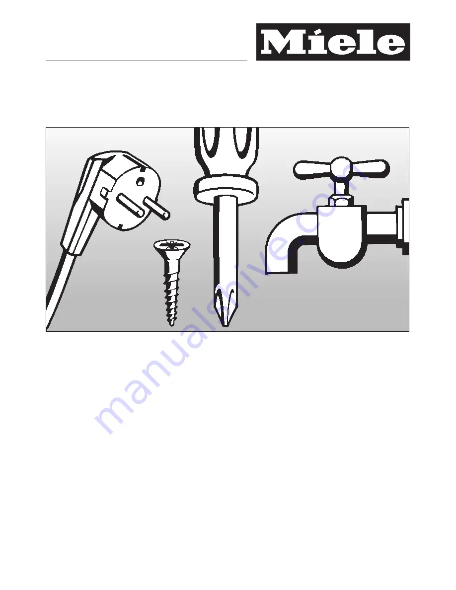
Page 11: ...nd Municipal codes and or local codes In Canada in accordance with the Canadian Electric code C22 1 latest edition Provincial and Municipal codes and or local codes Tools needed for installation Cutter with adjustable blade Cordless screwdriver T 20 Torx screwdriver T 20 Hammer drill for drilling holes in wall or floor Wood drills in different sizes Hammer Open end wrench SW 13 mm Box end wrench 5...
Page 12: ...urniture fixtures do not collide with the open door Before installation Caution the appliance is very heavy Use caution when unpacking and opening the door danger of tipping To protect the base from damage during installation attach a hard board linoleum etc to the floor in front of the intended installation location Take the supplied accessories out of the protective packaging There are transport...
Page 13: ...e the energy consumption of the appliance The slot for the RemoteVision module is located in the lower area of the back of your appliance Unscrew the screws a on the cover b and pull off the sticker c Remove the cover b Push the module into the slot until it locks into place Connect the appliance to the power supply and turn it on After several seconds the indicator light will come on The indicato...
Page 14: ...d wooden beam a can be placed behind the anti tip brackets b so the appliance can be securely attached to the base or wall The length of the wooden beam a should be to the width of the installation space If possible always screw the wooden beam into existing studs Mounting Accessories The mounting accessories needed for installing the appliance into the niche are included in the packaging Several ...
Page 15: ...nd right walls of the appliance niche Mark the holes through the anti tip brackets b on the floor of the installation niche Set the brackets aside Assure that there are no electrical wires or plumbing in the area which the screws could penetrate risk of injury and damage Drill pilot holes 1 8 3 mm for 5 x 60 mm wood screws 1 16 2 mm for 4 x 15 mm wood screws Tightly secure the anti tip brackets in...
Page 16: ...st cover the appliance by at least 2 50 8 mm Mark the installation height lower edge of the beam on the rear wall of the niche Select screws according to the thickness of the wooden beam Example 3 screw for 2x4 beam Determine the number of screws based on the cavity width to ensure that the beam will be attached securely Locate wall studs near the rear wall of the cavity and mark drill holes in th...
Page 17: ...t must be used for each appliance To prevent the power cord from becoming caught Tie a piece of string to the middle of the power cord and feed it forward under the appliance When sliding the appliance in pull the cable forward c Carefully slide the appliance into the space until the height adjustable wheels interlock with the anti tip brackets d If resistance is felt when attempting to slide the ...
Page 18: ...ottom e Rear with a 5 16 8 mm hex nut driver via flexible shaft f A mark is located on the appliance base and is used as a standard gauge for height adjustment When adjusting the height align this mark at 1 1 4 32 mm above the floor Unscrew the height adjustable feet until the mark on the base has reached the indicated guide dimension 1 1 4 32 mm Check that the appliance is level with the surround...
Page 19: ... installation niche Open the appliance door Fasten the appliance on the left and right hand sides with the 3 supplied wood screws If there is a fairly large gap above the appliance cut a wooden beam to fit exactly and place it in the gap Now connect the water supply to the appliance see Plumbing Attaching the toe kick cover The maximum height of the toe kick cover is 4 from the top of the floor Do...
Page 20: ... supply and exhaust air separate This prevents warm exhaust air from flowing into the machine optimizing the energy performance of the unit If necessary shorten the three parts of the air separator Insert the foam pieces back into the sides Open the freezer door Wedge the air separator at the bottom of the freezer door so it connects in place Installing the appliance 67 ...
Page 21: ...ows the dispenser to be aligned with the custom door to achieve the best possible appearance Disconnect the appliance from the power supply Press the dispenser back and pull downwards to remove Remove the cover and the plastic grill Remove the screw from the rear casing then lift the tab on the drip tray up and off Installing the appliance 68 ...
Page 22: ...he four clamps Insert a screwdriver into one of the four slots and push sideways until the dispenser is aligned with the custom door the gray arrow will adjust to the rear the black arrow will adjust front Re tighten the screws of the clamps Insert the drip tray back into place then clip the water sensors back onto the drip tray Replace the rear cover panel and screw Replace the drip tray and cove...
Page 23: ... with the door surface be sure the word TOP on the cover frame is upward For 1 1 2 38 mm thick custom doors Press the extension frame onto the cover frame Slide the cover frame onto the dispenser and press until it is flush with the door surface be sure the word TOP on the cover frame is upward Insert the cover frame Installing the appliance 70 ...
Page 24: ... cold water supply The water pressure must be between 25 and 120 psi 1 72 8 25 bar A separate shut off valve must be installed so that the water supply can be interrupted as needed The maximum outer diameter of the water pipe without fittings 3 8 10 mm The shut off valve for the water connection must not be located behind the appliance It is recommended to place the shut off valve directly next to...
Page 25: ...ng pipe to the shut off valve according to the instructions supplied by the manufacturer of the ice cube maker installation kit Install the connecting pipe Always observe the indicated clearance dimensions to prevent damage to the connecting pipe when pushing in the appliance Secure the connecting pipe to the floor with adhesive tape You may now proceed to install the appliance See Installing the ...
Page 26: ...ipe to suit the location of the connection on the appliance 2 Push the union nut and seal onto the water pipe Push the end of the water pipe into the appliance connection and screw on the union nut 3 First tighten by hand Then use an open ended wrench to tighten the union nut Do not over tighten Open the shut off valve and the main water connection Check for leaks at the connection for the shut of...
Page 27: ...ousehold electrical supply If there are any questions regarding the electrical connection of this appliance to the power supply please consult a licensed electrician or call the Miele Technical Service U1 800 999 1360 V1 800 565 6435 The appliance comes with a UL listed 3 wire power supply cord The appliance requires a 3 wire receptacle The receptacle must be installed by a licensed electrician on...
Page 28: ...Alteration rights reserved 3009 F 1471 SF For the most updated manual see the Miele web site M Nr 07 360 780 04 ...