MIDI hardware MBBS User Manual Download Page 6

Older keyboards, and especially those used in old analog organs, usually don't have 
such a thing, so in order to use 8x8 scanner, you must build diode matrix yourself, 
assuming it is possible to separate the contacts into groups of 8 keys. In other 
cases, when making diode matrix is impractical, you may use bus-bar type of 
scanners (BBS), where all keys share only one common bus. This is typical 
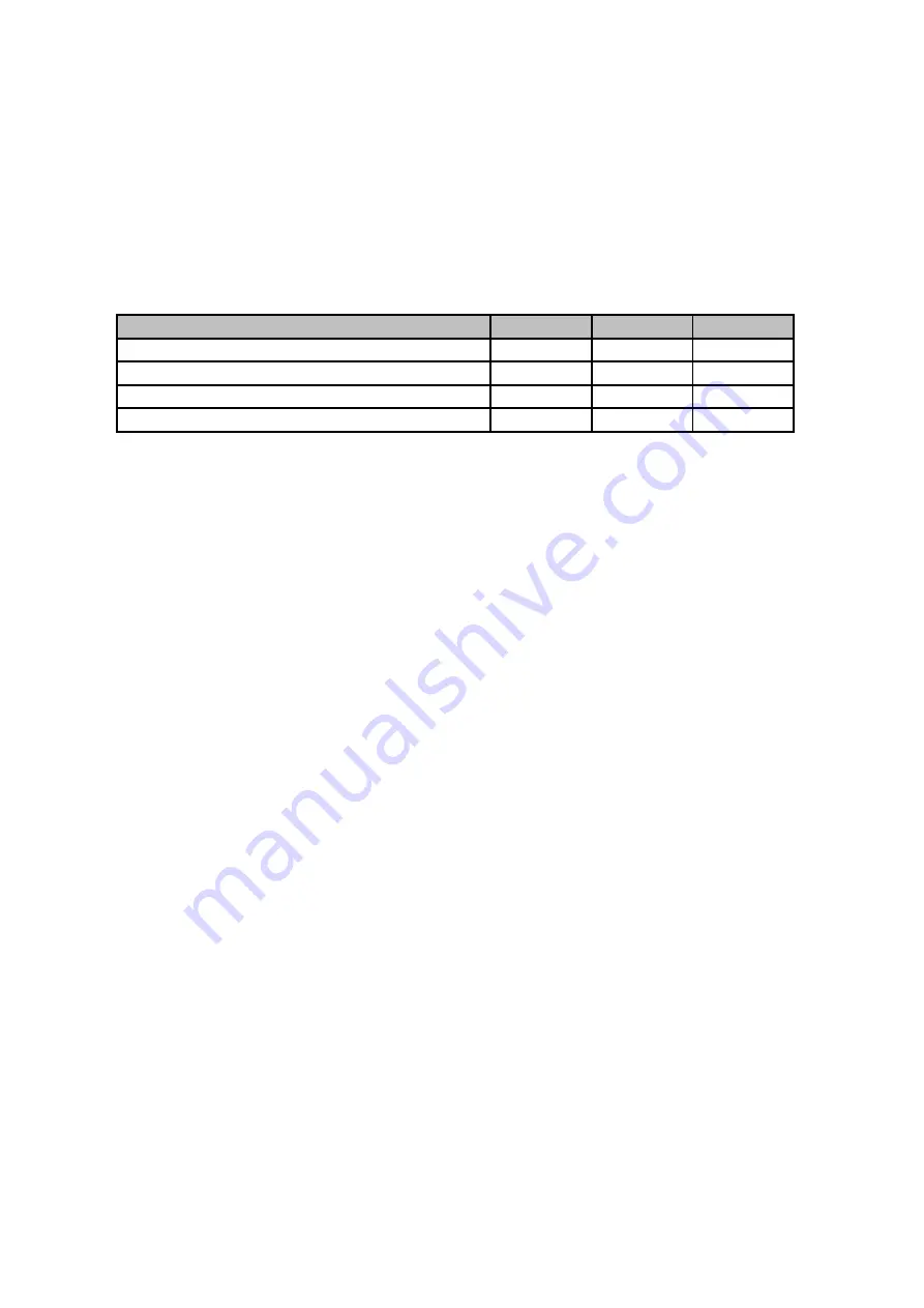
keyboard arrangement in all old organ consoles. Below is a short table showing 
which scanner type can be used with different keyboards:

Keyboard type

DMS

BBS

PDS

Independent switches, no connections

Switches organized in 8x8 diode matrix

Switches organized in 6x12 and other

One common rail for all switches

‡◊

‡◊

● - can be used directly
◊ - with additional diodes
‡ - requires rewiring of existing contacts.

 3.1 

Split for special function inputs - #905

By default all 63 on-board inputs are treated as keyboard interface, playing notes, 
or other similar MIDI events as described in chapter 5. But you can designate a few 
inputs for other tasks if less keyboard inputs are required. Such altered inputs work 
like they would be potentiometer inputs, but only with min and max values (0 and 
127) possible. If those buttons are assigned this way, each of them can be 
individually set to different event type and MIDI channel. It creates some new 
possibilities - for example you can assign transpose//- buttons, channel 
+/- buttons, and a few non-continuous CCs, with most obvious examples like 
Sustain or Portamento.
There can be up to 15 such inputs, and they are always placed at the top of note 
contacts, in the last, 4th connector (J4) of MBBS. This special mode is available 
only in MBBS and not in any of connected scanners.
To define the split point between normal note inputs, and special CC inputs, play 
any note at MBBS on-board inputs, enter command #905 from the keypad (or use 
on-board inputs in sequence: 64, 10, 1, 6), and then press the top key of desired 
note part. All inputs above this point, up to the EDIT input, will be now acting like 
inputs of POT scanner and can be individually programmed. To cancel this setting, 
and turn the whole range as normal inputs, repeat the procedure, but now set the 
split point at the last note input (63). Do NOT connect any potentiometer, or 
variable voltage to those inputs. They are only capable of working with switches, or 
logic levels. Applying other voltages may damage the board.
This kind of split has nothing to do with keyboard split described in chapter 5.5 and 
can be used independently of that one.

6

Summary of Contents for MBBS

Page 1: ...USER MANUAL for MBBS MIDI controller firmware version 2 0 www midi hardware com Roman Sowa 2011...

Page 2: ...12 5 2 7 Note off only 2133 12 5 2 8 One touch Patch Recall 2134 12 5 2 9 CC keyboard 2135 13 5 2 10 MIDI channel shift for all controls 2136 13 5 2 11 Small Transposer 2137 13 5 2 12 Big Transposer...

Page 3: ...25 7 6 6 Contact on off keyboard scanner mode 912 25 7 6 7 CC value pot scanner mode 913 25 7 6 8 Left split blink 916 25 7 6 9 Right split blink 917 25 7 6 10 All LEDs blink 918 25 7 6 11 Reset to d...

Page 4: ...ent transposition for all keyboards splits user defined MIDI channel for each keyboard split and pot user defined MIDI event for each pot and keyboard split up to 15 special function user defined inpu...

Page 5: ...there or at the minus GND supply lead of MBBS whatever is more convenient Additional keyboard switches may be connected to keyboard scanners There are several scanners available for 32 64 128 keys wi...

Page 6: ...0 and 127 possible If those buttons are assigned this way each of them can be individually set to different event type and MIDI channel It creates some new possibilities for example you can assign tra...

Page 7: ...of proper expanders like POT12 BBS24 PDS or BBSP They can be used as continuous controllers for things like volume modulation etc Usually those inputs would be connected to potentiometers but it s po...

Page 8: ...he table below More on how to enter digits and setting procedures in chapter 5 Default factory setting is 18ms keypad sequence 980 981 982 983 984 985 986 987 988 989 pot latency 5ms 7ms 9ms 13ms 18ms...

Page 9: ...itch This is the entry to EDIT mode and allows changing all settings of entire set Detailed procedures for all settings are described later in this chapter To make the settings more ergonomic and easi...

Page 10: ...the new position of the middle C MIDI note afterwards MIDI note number 36 You can select new position of middle C note anywhere between 3rd and top key of the keyboard 5 1 2 Transpose buttons Second...

Page 11: ...o enter 2 or 3 digits for each input controller depending on entered number To assign another one again you must turn the pot it a bit or play the key on another split and then start from 2 sequence f...

Page 12: ...nly one note played at a time with velocity set like described later and it is released just before new note is about to play Whole knob slow rotation plays 128 notes from entire MIDI range 5 2 6 Note...

Page 13: ...ber of semitones determined by pot position In the middle it gives no shift and full rotation covers range from 4 to 4 semitones It s most useful when pot is replaced by 9 position switch with 8 resis...

Page 14: ...becomes stop control in Ahlborn Archive organ sound module When a key is pressed MIDI controller 73 49 hex is sent when released MIDI controller 74 4A hex Value of the controller is determined by the...

Page 15: ...ler 71 47 hex is sent with value 64 127 and when it is released the same MIDI controller but with value lower by 64 5 2 21 3 note chord collect 2147 This mode of operation is used only for keyboard sc...

Page 16: ...is similar to transposition setting described in chapter 5 2 24 also you can have 1 semitone buttons events 156 157 and 1 octave buttons events 158 159 But there are 2 main differences Here transposit...

Page 17: ...S allows to send Program Change MIDI messages in range 1 128 Several ways are available here s summary of them series of Program Change buttons in continuous numbering range using event 129 described...

Page 18: ...button There can be 64 such buttons working in single MIDI channel Those buttons can be connected to any keyboard scanner MBBS will send the patch number in channel previously assigned to all those bu...

Page 19: ...ue of 2nd MIDI data byte in hex MIDI monitor should not be enabled at all times it increases MIDI latency and may cause dropped or hung notes if LCD is connected in one chain with other scanners To tu...

Page 20: ...aximum or minimum value of given MIDI parameter controlled by the pot Go to chapter 4 for more about potentiometer connection Keys must be connected in diode matrix exactly like in the schematics belo...

Page 21: ...on or by shorting to GND the 64th pin on MBBS board 3 enter 92 from numeric keypad or internal MBBS contact inputs pin 10th and then 3rd 4 enter one digit from range 1 4 the same way as you entered 92...

Page 22: ...nput so you can use 2 such boards connected to 1 MBBS input All 4 connectors for ribbon cable and the pinout are the same as used in BBSP see above Each black connector covers 16 keys BBS 1K must be c...

Page 23: ...ff and the one pressed lights up now If assigned to notes only MIDI note on is generated this is more suitable for use with Program Change 3 contact on off mode where button action is recognized as ty...

Page 24: ...IDI data transmitted by MBBS to MIDI OUT socket Each split can work in different mode with independent or dependent buttons generating CC values or contact on offs To have different MIDI events or cha...

Page 25: ...er When a button is pressed MBBS can then generate MIDI notes or any other MIDI event usable with a keyboard scanner This is the oposite to CC value mode described next To set this mode on a split you...

Page 26: ...oard If you reverse connections between those 2 sockets the board will not work and potentiometer movement will not result in any MIDI activity However this does not cause any damage to the POT12 boar...

Page 27: ...nge the way how MiDisp operates to some extent To do any settings on particular display module you must select it first and the only way of doing that is to press the button connected to MiDisp button...

Page 28: ...s the system in EDIT mode If MiDisp module is connected it is clearly indicated there To quit from EDIT mode without changing anything for example if was pressed by mistake simply enter 0 There s no c...

Reviews: