维修手册
Service Manual
, 2017 v1.0
7
/
11
the control box.
)
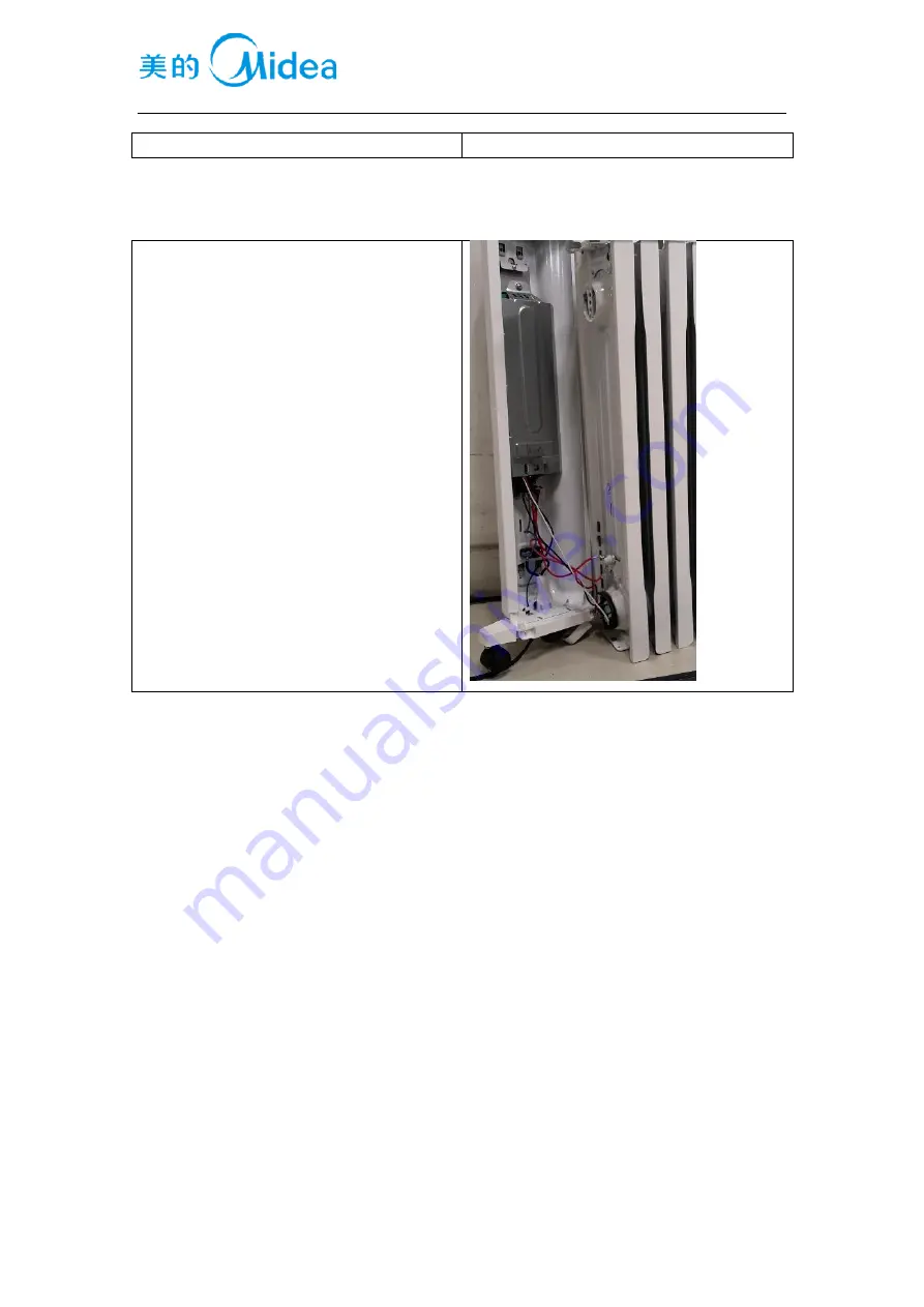
3.6
线束接线
wiring
disassemble
按如图将线束插好,在接线座组件、限温器、
发热管、倾倒开关的插线端子上焊锡。
(
Insert
the terminals referring to the picture. Then
solder the terminals connecting to tip-over
switch, heating element, temperature limiter
and terminal block assembly.
)


