background image

DM16-01.01.21en  

Mission 

On-off 

Service manual 


25 

  7. Installation Details 

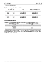
7.1 Wrench torque sheet for installation 

Outside diameter 

Torque 

Additional tightening torque 

mm inch 

N.cm 

N.cm 

Ф

6.35 1/4 

1500(153kgf.cm) 

1600(163kgf.cm) 

Ф

9.52 3/8 

2500(255kgf.cm) 

2600(265kgf.cm) 

Ф

12.7 1/2 

3500(357kgf.cm) 

3600(367kgf.cm) 

Ф

15.9 5/8 

4500(459kgf.cm) 

4700(479kgf.cm) 

Ф

19 3/4  6500(663kgf.cm) 

6700(683kgf.cm) 


7.2 Connecting the cables 

The power cord of connect should be selected according to the following specifications sheet. 

Rated current of appliance 

Nominal cross-sectional area (mm²) 

>3 and 

6 0.75 

>6 and 

10 1 

>10 and 

16 1.5 

>16 and 

25 2.5 

The cable size and the current of the fuse or switch are determined by the maximum current indicated 
on the nameplate which located on the side panel of the unit. Please refer to the nameplate before 
selecting the cable, fuse and switch. 


Summary of Contents for MOAB01-07HN1

Page 1: ...ce manual Mission ON OFF SERIES Service Manual 2016 MSMBA 07HRN1 W MOAB01 07HN1 MSMBA 09HRN1 W MOAB01 09HN1 MSMBB 12HRN1 W MOBA02 12HN1 MSMBC 19HRN1 W MOBA02 18HN1 MSMBD 24HRN1 W MOCA01 24HN1 DM16 01...

Page 2: ...cables 25 7 3 Pipe length and the elevation 26 7 4 Installation for the first time 27 7 5 Adding the refrigerant after running the system for many years 29 7 6 Re installation while the indoor unit n...

Page 3: ...e the correctly rated breaker of fuse There is risk of fire or electric shock Do not modify or extend the power cable There is risk of fire or electric shock Do not install remove or reinstall the uni...

Page 4: ...is risk of physical injury electric shock or product failure When the product is soaked contact an authorized service center There is risk of fire or electric shock Be caution that water could not ent...

Page 5: ...f the product when removing the air filter They are very sharp Do not step on or put anything on the product outdoor units Always insert the filter securely Clean the filter every two weeks or more of...

Page 6: ...2 Function Model Names of Indoor Outdoor Units On Off Capacity Indoor units Outdoor units 7k MSMBA 07HRN1 W MOAB01 07HN1 9k MSMBA 09HRN1 W MOAB01 09HN1 12k MSMBB 12HRN1 W MOBA02 12HN1 19k MSMBC 19HRN1...

Page 7: ...0 10492 13853 13853 Input W 702 735 712 732 955 995 Rated current RLA A 3 21 3 15 3 3 3 15 4 35 4 2 Locked rotor Amp LRA A 16 1 21 25 Thermal protector BF635 MA UP3 20 UP3 21 Thermal protector positio...

Page 8: ...inner groove tube f Coil length x height x width mm 685x504x13 37 685x504x13 37 745x508x22 g Number of circuits 2 2 2 Outdoor air flow HI m3 h Outdoor noise level dB A 52 52 56 Outdoor unit Dimension...

Page 9: ...protector UP3 64H Thermal protector position INTERNAL INTERNAL Capacitor uF 50 60 Refrigerant oil oil charge ml ESTEL OIL VG74 750 ESTER OIL VG74 850 Indoor fan motor Model YKFG 28 4 3 YKFG 45 4 22 I...

Page 10: ...se level dB A 58 5 60 5 Outdoor unit Dimension W D H mm 770x300x555 845x363x702 Packing W D H mm 900x345x585 965x395x755 Net Gross weight Kg 34 6 37 1 47 7 50 8 Refrigerant type g R410A 1200 R410A 180...

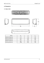
Page 11: ...1en Mission On off Service manual 11 4 Dimension 4 1 Indoor Unit Model W D H MSMBA 07HRN1 W 730 198 293 MSMBA 09HRN1 W 730 198 293 MSMBB 12HRN1 W 810 200 300 MSMBC 19HRN1 W 980 225 325 MSMBD 24HRN1 W...

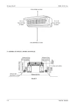
Page 12: ...Mission On off DM16 01 01 21en 12 Service manual For MSMBA 07HRN1 W MSMBA 09HRN1 W...

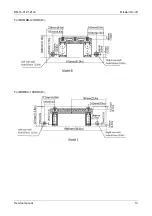
Page 13: ...DM16 01 01 21en Mission On off Service manual 13 For MSMBB 12HRN1 W For MSMBC 19HRN1 W...

Page 14: ...Mission On off DM16 01 01 21en 14 Service manual For MSMBD 24HRN1 W...

Page 15: ...DM16 01 01 21en Mission On off Service manual 15 4 2 Outdoor Unit More than 30cm More than 60cm More than 200cm More than 30cm More than 60cm Service space Fence or obstacles...

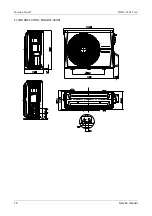
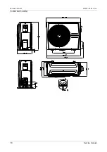
Page 16: ...Mission On off DM16 01 01 21en 16 Service manual For MOAB01 07HN1 MOAB01 09HN1...

Page 17: ...DM16 01 01 21en Mission On off Service manual 17 For MOBA02 12HN1 MOBA02 18HN1 487 W1 70 W2 298 555 300 D H 12 60 93 H1 H2 D1 770 W 779 W3 322 D2 25 B1 90 B2 61 5 A2 12 A1 R 6 286 D3...

Page 18: ...Mission On off DM16 01 01 21en 18 Service manual For MOCA01 24HN1...

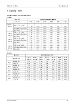
Page 19: ...kW 0 65 0 65 0 64 0 63 0 64 0 67 32 C D 23 C W Total capacity kW 2 39 2 36 2 34 2 30 1 84 1 72 Sensitive capacity kW 1 91 1 89 1 87 1 84 1 47 1 38 Input kW 0 73 0 73 0 72 0 71 0 73 0 75 Heating HEATI...

Page 20: ...0 84 0 84 0 82 0 84 0 88 32 C D 23 C W Total capacity kW 3 08 3 05 3 02 2 96 2 37 2 22 Sensitive capacity kW 2 46 2 44 2 41 2 37 1 89 1 77 Input kW 0 95 0 94 0 94 0 92 0 95 0 98 Heating HEATING OUTDOO...

Page 21: ...1 12 1 11 1 09 1 12 1 17 32 C D 23 C W Total capacity kW 4 10 4 06 4 02 3 94 3 15 2 96 Sensitive capacity kW 3 28 3 25 3 22 3 15 2 52 2 37 Input kW 1 26 1 25 1 25 1 22 1 26 1 31 Heating HEATING OUTDOO...

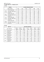
Page 22: ...1 78 1 76 1 73 1 78 1 85 32 C D 23 C W Total capacity kW 6 49 6 43 6 36 6 24 4 99 4 68 Sensitive capacity kW 5 19 5 14 5 09 4 99 3 99 3 74 Input kW 2 01 1 99 1 98 1 94 2 00 2 07 Heating HEATING OUTDOO...

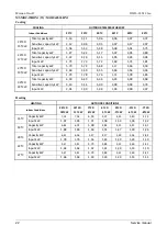
Page 23: ...57 2 55 2 50 2 58 2 68 32 C D 23 C W Total capacity kW 8 19 8 11 8 03 7 87 6 30 5 91 Sensitive capacity kW 6 55 6 49 6 42 6 30 5 04 4 72 Input kW 2 90 2 88 2 86 2 80 2 88 3 00 Heating HEATING OUTDOOR...

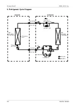
Page 24: ...ycle Diagram LIQUID SIDE GAS SIDE HEAT EXCHANGE EVAPORATOR HEAT EXCHANGE CONDENSER COMPRESSOR 2 WAY VALVE 3 WAY VALVE 4 WAY VALVE COOLING HEATING T2 Evaporator temp sensor T1 Room temp sensor ACCUMULA...

Page 25: ...cm 4700 479kgf cm 19 3 4 6500 663kgf cm 6700 683kgf cm 7 2 Connecting the cables The power cord of connect should be selected according to the following specifications sheet Rated current of applianc...

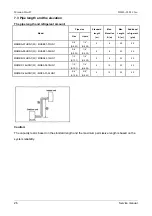
Page 26: ...s Liquid MSMBA 07HRN1 W MOAB01 07HN1 3 8 9 52 1 4 6 35 5 8 20 20 MSMBA 09HRN1 W MOAB01 09HN1 3 8 9 52 1 4 6 35 5 8 20 20 MSMBB 12HRN1 W MOBA02 12HN1 1 2 12 7 1 4 6 35 5 8 20 20 MSMBC 19HRN1 W MOBA02 1...

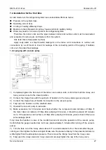
Page 27: ...the closed position 2 Connect the charge hose with the push pin of handle lo to the 3 way valves gas service port 3 Connect the charge hose of handle hi connection to the vacuum pump 4 Fully open the...

Page 28: ...arging cylinder and discharge the refrigerant by loosening the flare nut on the 2 way valve approximately 45 until the gauge indicates 0 3 to 0 5 Mpa 6 Disconnect the charge set and the charging cylin...

Page 29: ...ocedure 1 Connect the charge hose to the 3 way service port open the 2 way valve and the 3 way valve Connect the charge hose to the valve at the bottom of the cylinder If the refrigerant is R410A make...

Page 30: ...it quickly 4 Set the 2 way valve to the close position 5 Operate the air conditioner at the cooling cycle and stop it when the gauge indicates 0 1MPa 6 Set the 3 way valve to the closed position immed...

Page 31: ...Be sure to use a hexagonal wrench to operate the valve stems 7 Mount the valve stems nuts and the service port cap Be sure to use a torque wrench to tighten the service port cap to a torque 18N m Be s...

Page 32: ...the valves Low side on the charge set and charge the system with liquid refrigerant If the system cannot be charge with the specified amount of refrigerant or can be charged with a little at a time ap...

Page 33: ...above conditions certain safety protection features may come into operation and cause the unit to operate abnormally 2 The room relative humidity should be less than 80 If the air conditioner operate...

Page 34: ...ion on indoor display board Digital display Displays the temperature settings when the air conditioner is operational Displays the room temperature in FAN mode Displays the self diagnostic codes Dispa...

Page 35: ...during self clean operation if aplicable Dispalys under 8 heating operation WIFI control display WiFi kit is in standard Displays when the WIFI control feature is activated NOTE A guide on using the i...

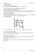
Page 36: ...an Speed is too low lower than 300RPM lasting 2 minutes the unit stops and LED displays failure information and can t returns to normal operation automatically 9 3 5 Current protection A B C Resume Th...

Page 37: ...in cooling mode 5 Auto fan High Low Medium 9 4 2 Cooling Mode 9 4 2 1 Compressor running rules When indoor room temp T1 is lower than setting value the compressor and outdoor fan will shut off T1 On...

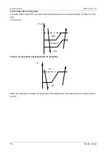
Page 38: ...e indoor fan runs all the time and the speed can be selected as high medium low and auto The auto fan T1 Ts High Low Medium 9 4 2 4 Low evaporator coil temperature T2 protection T2 On Off When the eva...

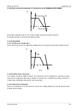
Page 39: ...n indoor room temp T1 is higher than setting value the compressor and outdoor fan will shut off T1 Off On 9 4 3 2 Outdoor fan running rules The outdoor units have single fan speed The outdoor fan will...

Page 40: ...indoor and outdoor motor will stop defrost lamp of the indoor unit will be lighted Will be displayed For MSMBD 24HRN1 W models AC will enter the defrosting mode according to the value of temp of T3 a...

Page 41: ...The compressor and outdoor fan keep running and the indoor fan runs at low speed After running for 30 minutes AC will turn to auto mode with 24 setting temperature Forced auto mode The action of force...

Page 42: ...how EC when the outdoor unit detects refrigerant leakage When compressor is active the value of the Coil temperature of evaporator T2 has no change or very little change 9 4 9 8 Heating When the compr...

Page 43: ...fan speed has been out of control 5 times X E5 Indoor room temperature sensor T1 open circuit or short circuit 6 times X E6 Evaporator coil temperature sensor T2 open circuit or short circuit 7 times...

Page 44: ...diagnosis and solution E1 Error Code E1 Malfunction decision conditions Indoor or outdoor PCB main chip does not receive feedback from EEPROM chip Supposed causes Installation mistake PCB faulty Troub...

Page 45: ...tection error diagnosis and solution E2 Error Code E2 Malfunction decision conditions When PCB does not receive zero crossing signal feedback for 4 minutes or the zero crossing signal time interval is...

Page 46: ...trol diagnosis and solution E3 Error Code E3 Malfunction decision conditions When indoor fan speed keeps too low 300RPM for certain time the unit will stop and the LED will display the failure Suppose...

Page 47: ...or Power on and set the unit running in fan mode at high fan speed After running for 15 seconds measure the voltage of pin1 and pin2 If the value of the voltage is less than 100V 208 240V power supply...

Page 48: ...cision conditions If the sampling voltage is lower than 0 06V or higher than 4 94V the LED will display the failure Supposed causes Wiring mistake Sensor faulty Trouble shooting Check the connection b...

Page 49: ...ot keep continuous 4 seconds and this situation happens 3 times the display area will show EC and AC will turn off Supposed causes T2 sensor faulty Indoor PCB faulty System problems such as leakage or...

Page 50: ...or outdoor unit s communication diagnosis and solution E9 Error Code E9 Malfunction decision conditions Indoor unit does not receive the feedback from outdoor unit during 120 seconds Supposed causes W...

Page 51: ...the temperature sensor from PCB measure the resistance value with a tester Temperature Sensors Room temp T1 sensor Indoor coil temp T2 sensor Outdoor coil temp T3 sensor Outdoor ambient temp T4 sensor...

Page 52: ...37 99 5 87359 77 171 1 29078 117 243 0 38991 2 28 39 8239 38 100 5 62961 78 172 1 25423 118 244 0 37956 1 30 37 1988 39 102 5 39689 79 174 1 2133 119 246 0 36954 0 32 35 2024 40 104 5 17519 80 176 1 1...

Page 53: ...5 167 8 084 115 239 2 422 4 25 222 8 36 97 34 32 76 169 7 82 116 241 2 357 3 27 211 4 37 99 32 94 77 171 7 566 117 243 2 294 2 28 200 7 38 100 31 62 78 172 7 321 118 244 2 233 1 30 190 5 39 102 30 36...

Reviews: