


Page 13
Outdoor Unit
Installation
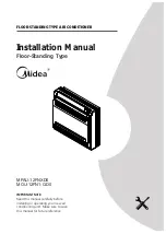
Table 5.1: Length Specifications of Split
Type Outdoor Unit (unit: mm/inch)
Split Type Outdoor Unit
(Refer to Fig 5.4, 5.5, 5.6, 5.7 and Table 5.1)
Fig. 5.6
Fig. 5.5
A
B
D
W
H
W
H
Fig. 5.4
Outdoor Unit Dimensions
W x H x D
Mounting Dimensions
Distance A Distance B
760x590x285 (29.9x23.2x11.2)
530 (20.85)
290 (11.4)
780x540x250 (30.7x21.25x9.85)
549 (21.6)
276 (10.85)
810x558x310 (31.9x22x12.2)
549 (21.6)
325 (12.8)
845x700x320 (33.27x27.5x12.6)
560 (22)
335 (13.2)
845x702x363 (33.27x27.6x14.3)
540 (21.26)
350 (13.8)
770x555x300 (30.3x21.85x11.8)
487 (19.2)
298 (11.7)
800x554x333 (31.5x21.8x13.1)
514 (20.24)
340 (13.39)
Outdoor Unit Types and Specifications
NOTE:
The minimum distance between the
outdoor unit and walls described in the
installation guide does not apply to airtight
rooms. Be sure to keep the unit unobstructed
in at least two of the three directions (M, N, P)
(See Fig. 5.7)
M
N
P
30 cm / 11.8” from back wall
60 cm / 23.6” on right
60
cm
/ 2
3.
6”
ab
ov
e
30 cm / 11.8” on left
200 cm / 78” in fron
t
Fig. 5.7
Fig. 5.8
L
H
300 cm / 118” or more
A
60 cm / 23.6”
or more
150 cm / 59”
or more
25 cm / 9.8”
or more
25 cm / 9.8”
or more
Rows of series installation
L
≤
H
L
≤
1/2H
L
A
25 cm / 9.8” or more
1/2H < L
≤
H
30 cm / 11.8” or more
L
>
H
Can not be installed
Table 5.2 The relations between H, A and L
are as follows.


