background image

29

Maintenance

4.7 

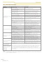
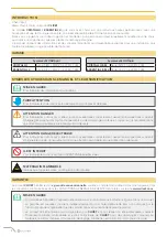
Indoor unit error codes

Error code

Cause

Number of 

flashes per 

second

Timer 

indicator

E0

EEPROM (Electrically Erasable Programmable Read-Only Memory) 

error of the indoor unit

1

Off

E1

Communication error between an indoor unit and the outdoor unit

2

Off

E3

Malfunction of the indoor unit fan speed

4

Off

E4

Internal room temperature sensor error

5

Off

E5

Evaporator coil temperature sensor error

6

Off

EC

Malfunctioning of the refrigerant leak detection system

7

Off

EE

Water level alarm failure

8

Off

E8

Communication error between two indoor units (only in systems 

with multiple indoor units)

9

Off

E9

Other malfunction of the two-unit model

10

Off

F0

Overload protection

1

On

F1

External temperature sensor error

2

On

F2

External condenser pipe sensor error

3

On

F3

Exhaust air temperature sensor error

4

On

F4

Outdoor unit EEPROM (Electrically Erasable Programmable 

Read-Only Memory) error

5

On

F5

Malfunction of the outdoor unit fan speed

6

On

P0

IPM protection of the inverter module

1

Flashing

P1

High/low voltage protection

2

Flashing

P2

Compressor overheating protection

3

Flashing

P3

Low outside temperature protection

4

Flashing

P4

Compressor drive error

5

Flashing

P5

Mode conflict

6

Flashing

P6

Compressor low pressure protection

7

Flashing

P7

External IGBT sensor error

8

Flashing

FA

Malfunction of communication with the indoor unit

11

On

88

Malfunction of communication with the indoor unit

-

-

Summary of Contents for CLIVET CRISTALLO

Page 1: ...CRISTALLO Serie IM1 XY da 20M a 70M ESSENTIAL 2 Serie IL2 XY da 20M a 70M MANUALE PER L INSTALLAZIONE L USO E LA MANUTENZIONE M0P300002 03 12 20 I GB F...

Page 2: ...zionamenti o danni materiali all apparecchio richiedono quindi particolare attenzione ed adeguata preparazione f ATTENZIONE PERICOLO ELETTRICO Per indicare azioni che se non effettuate correttamente p...

Page 3: ...bi e i cavi 17 2 4 8 Montaggio dell unit interna 18 3 Uso 19 3 1 Descrizione componenti del sistema 19 3 2 Significato dei codici del display 19 3 3 Telecomando 20 3 4 Funzionamento 20 3 4 1 Altre fun...

Page 4: ...one e le parti specificate L uso di componenti non standard pu provocare perdite d acqua scosse elettriche o incendi e causare malfunzionamenti dell unit Non usare mezzi diversi da quelli consigliati...

Page 5: ...ttore staccare la spina dalla presa di alimentazione elettrica e contattare un rivenditore autorizzato L uso dell apparecchio ai bambini ed alle persone con ridotte capacit o con mancanza di esperienz...

Page 6: ...ubo flessibile di drenaggio 7 Collegamento elettrico 8 Linee frigorifere 9 Alimentazione unit esterna 10 Telecomando 11 Supporto del telecomando 12 Display led CRISTALLO 13 Display led ESSENTIAL 2 l A...

Page 7: ...l display LCD 7 Aletta di ventilazione verticale 8 Tasto di comando manuale sul retro 9 Supporto del telecomando Unit esterna 10 Tubo di scarico tubo di collegamento del refrigerante 11 Cavo di colleg...

Page 8: ...Quantit Piastra di montaggio 1 Tassello 5 Vite di fissaggio per piastra di montaggio ST3 9 X 25 5 Telecomando 1 Supporto del telecomando 1 Vite di fissaggio per supporto del telecomando ST2 9 x 10 2 B...

Page 9: ...tazionali dell apparecchio e quanto richiesto dalla Legislazione in vigore Etichetta matricolare Unit interna Fig 3 m PRESTARE CAUTELA La manomissione l asportazione la mancanza delle etichette di ide...

Page 10: ...sizioni dei codici elettrici nazionali e locali Tutti i collegamenti elettrici devono essere eseguiti secondo lo schema elettrico riportato sui pannelli delle unit interna ed esterna Se l impianto ele...

Page 11: ...ssere d aiuto per la scelta di una posizione adatta per l unit interna Il luogo di installazione deve presentare le seguenti caratteristiche buona circolazione d aria facilit di drenaggio il rumore em...

Page 12: ...m Min 2 3 m Min 12 cm Min 12 cm Fig 4 A Posizione del display CRISTALLO e del ricevitore del segnale da telecomando B Posizione del display ESSENTIAL 2 e del ricevitore del segnale da telecomando NOTA...

Page 13: ...2 mm 517 4 mm 144 mm 138 mm Modello 35M Modello 20M 27M Foro nel muro lato posteriore sinistro 65 mm Foro nel muro lato posteriore sinistro 65 mm Foro nel muro lato posteriore destro 65 mm Foro nel mu...

Page 14: ...lencati al paragrafo 2 4 1 Locale di installazione per informazioni dettagliate sulle dimensioni della piastra di montaggio vedere Dimensioni della piastra di montaggio 3 Realizzare i fori per le viti...

Page 15: ...taggio Come ausilio per la scelta della posizione ottimale fare riferimento al punto Dimensioni della piastra di montaggio Il foro nella parete dovr avere un diametro minimo di 65 mm 90 mm per i model...

Page 16: ...i potrebbe danneggiare la griglia anteriore 4 Usando una forbice tagliare il manicotto isolante in modo da esporre circa 15 cm delle linee frigorifere Questa operazione ha una doppia utilit facilita i...

Page 17: ...nsa 5 Rimuovere il filtro aria e versare una piccola quantit d acqua nella vaschetta di scarico per verificare che l acqua defluisca correttamente dall unit l AVVERTENZA Per evitare perdite indesidera...

Page 18: ...tura identificare chiaramente i cavi sotto tensione L e gli altri cavi 2 Aprire il pannello anteriore dell unit interna 3 Usando un cacciavite aprire il coperchio del vano morsetti sul lato destro del...

Page 19: ...nit Linee frigorifere Nastro isolante Cavi elettrici Tubo di drenaggio Fig 16 m PRESTARE CAUTELA Fare in modo che il tubo di drenaggio si trovi nella parte inferiore del gruppo La disposizione del tub...

Page 20: ...gancio superiore della piastra di montaggio 2 Usare una staffa o un cuneo per sollevare l unit in modo da avere spazio sufficiente per collegare le linee frigorifere i cavi elettrici e il tubo di dre...

Page 21: ...ne TIMER ON vengono attivate le funzioni SWING TURBO o SILENCE Si visualizza per 3 secondi quando si imposta il timer di accensione TIMER OFF vengono disattivate le funzioni SWING TURBO o SILENCE Quan...

Page 22: ...OW MED HIGH Nota tenendo premuto il tasto per 2 secondi viene attivata la funzione Silence FUNZIONALIT AVANZATE fare riferimento al Manuale del telecomando TEMP Riduce la temperatura a decrementi di 1...

Page 23: ...ria REGOLAZIONE DELL ANGOLAZIONE VERTICALE DEL FLUSSO D ARIA Con l unit accesa usare il tasto per regolare la direzione angolazione verticale del flusso d aria 1 Premere una volta il tasto per attivar...

Page 24: ...ni 3 5 Funzionamento manuale senza telecomando Nel caso in cui il telecomando non funzioni l unit pu essere azionata manualmente con il tasto di comando manuale situato sull unit interna Si noti che l...

Page 25: ...cie in plastica usare acqua a temperature superiori a 40 C per pulire il pannello anteriore L acqua molto calda pu causare la deformazione o lo scolorimento del pannello 4 2 Pulizia del filtro dell ar...

Page 26: ...un po d acqua Batteria unit esterna Fig 27 4 4 Periodi di inutilizzo prolungato Se si prevede di non utilizzare il condizionatore per un periodo prolungato procedere come segue Pulire tutti i filtri...

Page 27: ...lazione torna alla posizione originale Si sente uno scricchiolio dopo l attivazione del modo Riscaldamento a causa dell espansione e della contrazione delle parti in plastica dell unit Sia l unit inte...

Page 28: ...le batterie attiva la funzione di protezione con ritardo di 3 minuti Attendere tre minuti prima di riavviare l unit attivo il timer Disattivare il timer L unit si avvia o si arresta frequentemente La...

Page 29: ...a due unit 10 Off F0 Protezione da sovraccarico 1 On F1 Errore del sensore di temperatura esterna 2 On F2 Errore del sensore del tubo del condensatore esterno 3 On F3 Errore del sensore di temperatur...

Page 30: ...i RAEE originati dai nuclei domestici e i RAEE di origine commerciale industriale istituzionale e di altro tipo analoghi per natura e quantit a quelli originati dai nuclei domestici I rifiuti delle A...

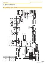
Page 31: ...31 Allegati 6 ALLEGATI 6 1 Schemi elettrici unit interna Cn11 CN1 SERIE GRANDEZZA IM1 XY 20M 27M 35M 53M 70M IL2 XY 20M 27M 35M 53M 70M...

Page 32: ...30 UE electromagnetic compatibility compatibilit elettromagnetica Elektromagnetische Vertr glichkeit compatibilit lectromagn tique compatibilidad electromagn tica 2009 125 CE Ecodesign Progettazione e...

Page 33: ...agnetic compatibility compatibilit elettromagnetica Elektromagnetische Vertr glichkeit compatibilit lectromagn tique compatibilidad electromagn tica 2009 125 CE Ecodesign Progettazione ecocompatibile...

Page 34: ...34 Allegati...

Page 35: ...35 Allegati...

Page 36: ...it DA 30 ANNI OFFRIAMO SOLUZIONI PER IL COMFORT SOSTENIBILE E IL BENESSERE DELL INDIVIDUO E DELL AMBIENTE www clivet com vendita e assistenza ASSISTENZA DEDICATA PRONTO CLIVET Assistenza SPLIT Clivet...

Page 37: ...CRISTALLO IM1 XY series from 20M to 70M ESSENTIAL 2 IL2 XY series from 20M to 70M MANUAL FOR INSTALLATION USE AND MAINTENANCE GB...

Page 38: ...alfunctions or material damage to the device therefore they require special attention and adequate preparation f ATTENTION ELECTRIC DANGER To indicate actions which if not carried out correctly may re...

Page 39: ...8 2 4 7 Wrap the pipes and cables 19 2 4 8 Mounting the indoor unit 20 3 Use 21 3 1 Description of system components 21 3 2 Meaning of the display codes 21 3 3 Remote control 22 3 4 Operation 22 3 4 1...

Page 40: ...e of non standard components may cause water leakage electric shock or fire and cause the unit to malfunction Do not use any means other than those recommended by the manufacturer to accelerate the de...

Page 41: ...th metal parts of the appliance disconnect the switch unplug it from the power supply socket and contact an authorised dealer Use of the appliance by children and persons with reduced capacity or lack...

Page 42: ...nit 6 Flexible drainage hose 7 Electrical connection 8 Refrigerant piping 9 Outdoor unit power supply 10 Remote control 11 Remote control support 12 Display led CRISTALLO 13 Display led ESSENTIAL 2 l...

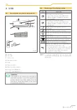
Page 43: ...lation flap 6 LCD display window 7 Vertical ventilation flap 8 Manual control button on the back 9 Remote control support Outdoor unit 10 Drain pipe refrigerant connection pipe 11 Connection cable 12...

Page 44: ...lustration Waiting Quantity Mounting plate 1 Gusset 5 Fixing screw for mounting plate ST3 9 X 25 5 Remote control 1 Remote control support 1 Fixing screw for the ST2 9 x 10 remote control holder 2 AAA...

Page 45: ...shows the technical and performance data of the unit and what is required by the legislation in force Serial number label Indoor unit Fig 3 m CAUTION Tampering removal lack of identification labels o...

Page 46: ...one by a licensedelectricianaccordingtotheprovisions of national and local electrical codes All electrical connections must be made according to the wiring diagram on the panels of the indoor and outd...

Page 47: ...location for the indoor unit The installation location must have the following characteristics good air circulation ease of drainage the noise emitted by the unit must not disturb other people stabil...

Page 48: ...in 15 cm Min 2 3 m Min 12 cm Min 12 cm Fig 4 A Position of the display CRISTALLO and remote control signal receiver B Position of the display ESSENTIAL 2 and remote control signal receiver NOTE The re...

Page 49: ...4 mm 144 mm 138 mm 35M Model 20M 27M Model Hole in the wall on the left rear side 65 mm Hole in the wall on the left rear side 65 mm Hole in the wall on the right rear side 65 mm Hole in the wall on t...

Page 50: ...n that meets the requirements listed in paragraph 2 4 1 Installation room for detailed information on the dimensions of the mounting plate see Mounting plate dimensions 3 Drill the holes for the fixin...

Page 51: ...he mounting plate To help you choose the optimal position refer to point Mounting plate dimensions The hole in the wall should have a minimum diameter of 65 mm 90 mm for 70M models and a slight downwa...

Page 52: ...cut panel as this may damage the front grille 4 Using scissors cut the insulation sleeve so that about 15 cm of the refrigerant piping is exposed This operation has a double utility it facilitates co...

Page 53: ...sation from forming 5 Remove the air filter and pour a small amount of water into the drain pan to make sure the water is draining properly from the unit l WARNING To prevent unwanted leakage the unus...

Page 54: ...tors m CAUTION When crimping clearly identify live cables L and other cables 2 Open the front panel of the indoor unit 3 Using a screwdriver open the terminal compartment cover on the right side of th...

Page 55: ...coolant pipes and cables as indicated in Fig 16 Indoor unit Space behind the unit Refrigerant piping Insulating tape Electric cables Drainage pipe Fig 16 m CAUTION Make sure that the drainage pipe is...

Page 56: ...p of the indoor unit to the top hook of the mounting plate 2 Use a bracket or wedge to lift the unit so that there is enough space to connect the refrigerant piping electrical cables and drainage pipe...

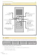
Page 57: ...TIMER ON SWING TURBO or SILENCE functions are activated It displays for 3 seconds when you set the start up timer TIMER OFF SWING TURBO or SILENCE functions are deactivated When the function against c...

Page 58: ...HEAT FAN FAN Used to select the fan speed among the following options AUTO LOW MED HIGH Note Pressing and holding the key for 2 seconds activates the Silence function ADVANCED FEATURES refer to the Re...

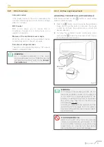
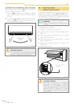
Page 59: ...ection vertical angle 1 Press the button once to activate the ventilation louver Each time the button is pressed the louver is tilted by 6 Press the button until you reach the desired direction 2 To s...

Page 60: ...on located on the indoor unit Note that manual operation is only a temporary solution and it is highly recommended to run the unit with the remote control l WARNING Before activating the unit manually...

Page 61: ...deformation of the plastic surface use water at temperatures above 40 C to clean the front panel Very hot water can cause the panel to deform or discolour 4 2 Cleaning the air filter Obstruction of t...

Page 62: ...or unit battery Fig 27 4 4 Extended periods of inactivity If you do not plan to use the air conditioner for an extended period of time proceed as follows Clean all filters ActivatetheVentilationmodeun...

Page 63: ...eturns to its original position You will hear a crackling sound after the Heating mode is activated due to the expansion and contraction of the plastic parts of the unit Both the indoor and outdoor un...

Page 64: ...Replace batteries Protection function with 3 minute delay is active Wait three minutes before restarting the unit The timer is active Deactivate the timer The unit starts or stops frequently The amou...

Page 65: ...9 Off E9 Other malfunction of the two unit model 10 Off F0 Overload protection 1 On F1 External temperature sensor error 2 On F2 External condenser pipe sensor error 3 On F3 Exhaust air temperature se...

Page 66: ...nating from private households and WEEE which comes from commercial industrial institutional and other sources which because of its nature and quantity is similar to that from private households Subje...

Page 67: ...31 Attachments 6 ATTACHMENTS 6 1 Indoor unit wiring diagrams Cn11 CN1 SERIE SIZE IM1 XY 20M 27M 35M 53M 70M IL2 XY 20M 27M 35M 53M 70M...

Page 68: ...0 UE electromagnetic compatibility compatibilit elettromagnetica Elektromagnetische Vertr glichkeit compatibilit lectromagn tique compatibilidad electromagn tica 2009 125 CE Ecodesign Progettazione ec...

Page 69: ...magnetic compatibility compatibilit elettromagnetica Elektromagnetische Vertr glichkeit compatibilit lectromagn tique compatibilidad electromagn tica 2009 125 CE Ecodesign Progettazione ecocompatibile...

Page 70: ...34 Attachments...

Page 71: ...35 Attachments...

Page 72: ...Villapaiera 32032 Feltre BL Italy Tel 39 0439 3131 Fax 39 0439 313300 info clivet it FOR 30 YEARS WE HAVE BEEN OFFERING SOLUTIONS FOR SUSTAINABLE COMFORT THE WELL BEING OF PEOPLE AND THE ENVIRONMENT w...

Page 73: ...CRISTALLO S rie IM1 XY de 20M 70M ESSENTIAL 2 S rie IL2 XY de 20M 70M MANUEL POUR L INSTALLATION L UTILISATION ET L ENTRETIEN F...

Page 74: ...dysfonctionnements ou des dommages mat riels l appareil ils requi rent donc une attention particuli re et une pr paration ad quate f ATTENTION DANGER LECTRIQUE Pour indiquer les actions qui si elles...

Page 75: ...triques 18 2 4 7 Enrouler les tuyaux et les c bles 19 2 4 8 Montage de l unit interne 20 3 Utilisation 21 3 1 Description des composants du syst me 21 3 2 Signification des codes l cran 21 3 3 T l com...

Page 76: ...e composants non standard peut entra ner des fuites d eau des d charges lectriques ou des incendies et provoquer un dysfonctionnement de l unit Ne pas utiliser d autres moyens que ceux recommand s par...

Page 77: ...de d brancher la fiche de la prise de courant car dans ce cas il faut contacter un revendeur agr De laisser des enfants et des personnes capacit s r duites ou manquant d exp rience et de connaissances...

Page 78: ...rne 6 Tuyau flexible de drainage 7 Branchement lectrique 8 Lignes frigorifiques 9 Alimentation des unit s externes 10 T l commande 11 Support de la t l commande 12 cran LED CRISTALLO 13 cran LED ESSEN...

Page 79: ...Fen tre de l cran LCD 7 Volet de ventilation vertical 8 Touche de commande manuelle l arri re 9 Support de la t l commande Unit externe 10 Tuyaudevidange tuyauderaccordementdur frig rant 11 C ble de r...

Page 80: ...escription Aspect Quantit Plaque de montage 1 Cheville 5 Vis de fixation pour plaque de montage ST3 9 X 25 5 T l commande 1 Support de la t l commande 1 Vis de fixation pour support de la t l commande...

Page 81: ...es les performances de l appareil et ce qui est requis par la l gislation en vigueur en la mati re tiquette du num ro de s rie Unit interne Fig 3 m FAIRE ATTENTION L alt ration le retrait le d faut d...

Page 82: ...codes lectriques nationaux et locaux Tous les branchements lectriques doivent tre effectu s selon le sch ma lectrique figurant sur les panneaux des unit s interne et externe Si l installation lectriq...

Page 83: ...it interne Le site d installation doit avoir les caract ristiques suivantes bonne circulation d air facilit de drainage le bruit mis par l unit ne doit pas d ranger d autres personnes stabilit etsolid...

Page 84: ...5 cm Min 2 3 m Min 12 cm Min 12 cm Fig 4 A Position de l cran CRISTALLO et du r cepteur du signal de la t l commande B Position de l cran ESSENTIAL 2 et du r cepteur du signal de la t l commande REMAR...

Page 85: ...2 mm 517 4 mm 144 mm 138 mm Mod le 35M Mod le 20M 27M Trou dans le mur c t arri re gauche 65 mm Trou dans le mur c t arri re gauche 65 mm Trou dans le mur c t arri re droit 65 mm Trou dans le mur c t...

Page 86: ...phe 2 4 1 Pi ce pour l Installation pour des informations d taill es sur les dimensions de la plaque de montage voir Dimensions de la plaque de montage 3 Percer les trous pour les vis de fixation dans...

Page 87: ...ider choisir la position optimale voir le point Dimensions de la plaque de montage Le trou dans le mur doit avoir un diam tre minimum de 65 mm 90 mm pour les mod les 70M et une l g re inclinaison vers...

Page 88: ...anneau pr d coup car cela pourrait endommager la grille avant 4 l aide de ciseaux couper le manchon isolant de mani re d gager environ 15 cm des lignes frigorifiques Cette op ration a un double utilit...

Page 89: ...e air et verser une petite quantit d eau dans le bac de vidange pour v rifier que l eau s coule correctement de l unit l MISE EN GARDE Pour viter les fuites non souhait es le trou de vidange inutilis...

Page 90: ...des conducteurs m FAIRE ATTENTION Lors du sertissage il faut identifier clairement les fils sous tension L et les autres fils 2 Ouvrir le panneau avant de l unit interne 3 l aide d un tournevis ouvri...

Page 91: ...orifiques Ruban isolant C bles lectriques Tuyau de drainage Fig 16 m FAIRE ATTENTION S assurer que le tuyau de drainage se trouve dans la partie inf rieure de l unit La disposition du tuyau de drainag...

Page 92: ...plaque de montage 2 Utiliser un support ou une cale pour soulever l unit afin qu il y ait suffisamment d espace pour connecter les lignes frigorifiques les c bles lectriques et le tuyau de drainage v...

Page 93: ...es fonctions SWING TURBO ou SILENCE S affiche pendant 3 secondes lors de la configuration du timer de marche TIMER OFF de la d sactivation des fonctions SWING TURBO ou SILENCE de l activation de la fo...

Page 94: ...OW MED HIGH Remarque en appuyant sur la touche pendant 2 secondes la fonction Silence s active FONCTIONS AVANC ES voir le manuel de la t l commande TEMP Diminue la temp rature par paliers de 1 C La te...

Page 95: ...l angle du flux d air R GLAGE DE L ANGLE VERTICAL DU FLUX D AIR Avec l unit allum e utiliser la touche pour r gler le sens angle vertical du flux d air 1 Appuyer une fois sur la touche pour activer l...

Page 96: ...mmande Si la t l commande ne fonctionne pas l unit peut tre actionn e manuellement l aide de la touche de commande manuelle situ e sur l unit interne Il faut noter que le fonctionnement manuel ne doit...

Page 97: ...ormations de la surface en plastique d utiliser de l eau des temp ratures sup rieures 40 C pour nettoyer le panneau avant De l eau tr s chaude peut d former ou d colorer le panneau 4 2 Nettoyage du fi...

Page 98: ...nit externe Fig 27 4 4 P riodes d inutilisation prolong e En cas de d cision de ne pas utiliser le climatiseur pendant une p riode prolong e il faut proc der comme suit Nettoyer tous les filtres Actio...

Page 99: ...origine Un grincement s entend apr s l activation du mode Chauffage cause de la dilatation et de la r traction des pi ces en plastique de l unit Les unit s interne et externe sont bruyantes L ger siff...

Page 100: ...placer les piles La fonction de protection avec retard de 3 minutes est activ e Attendre trois minutes avant de red marrer l unit Le timer est activ D sactiver le timer L unit d marre ou s arr te fr q...

Page 101: ...tionnement du mod le deux unit s 10 Off F0 Protection de surcharge 1 On F1 Erreur du capteur de temp rature ext rieure 2 On F2 Erreur du capteur du tuyau du condenseur externe 3 On F3 Erreur du capteu...

Page 102: ...d origine commerciale industrielle institutionnelle et d autres types de nature et de quantit semblables ceux provenant des foyers domestiques Les d chets des EEE qui pourraient tre utilis s la fois...

Page 103: ...31 Pi ces jointes 6 PI CES JOINTES 6 1 Sch mas lectrique de l unit interne Cn11 CN1 S RIE TAILLE IM1 XY 20M 27M 35M 53M 70M IL2 XY 20M 27M 35M 53M 70M...

Page 104: ...4 30 UE electromagnetic compatibility compatibilit elettromagnetica Elektromagnetische Vertr glichkeit compatibilit lectromagn tique compatibilidad electromagn tica 2009 125 CE Ecodesign Progettazione...

Page 105: ...romagnetic compatibility compatibilit elettromagnetica Elektromagnetische Vertr glichkeit compatibilit lectromagn tique compatibilidad electromagn tica 2009 125 CE Ecodesign Progettazione ecocompatibi...

Page 106: ...34 Pi ces jointes...

Page 107: ...35 Pi ces jointes...

Page 108: ...aiera 32032 Feltre BL Italie T l 39 0439 3131 Fax 39 0439 313300 info clivet it DEPUIS PLUS DE 30 ANS NOUS OFFRONS DES SOLUTIONS POUR UN CONFORT DURABLE ET LE BIEN TRE DES PERSONNES ET DE L ENVIRONNEM...

Reviews: