background image

SECTION 4 

MAINTENANCE 


38 

C.  Reassembly of Air Fingers 

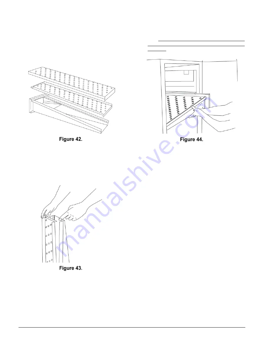
1.  Gather the air finger parts for reassembly.  Air 

fingers are made up of one inner plate, one outer 

plate, and the finger housing manifold. Be sure to 

match up the markings (T1, T2, T3, etc.) on all the 

parts of each air finger. 


2.  Reassemble each finger by first inserting the inner 

plate into the housing. Keep your fingers clear so 

you won’t pinch them. The inner plate of a finger 

will only go in one way because of its design. 

3.  Replace each outer plate by placing your hands 

flat on the top of the plate and pushing down. Keep 

your fingers clear so you won’t pinch them. 


4.  Reinstall the air fingers by pushing in at the back 

side. Remember to replace them according to the 

numbers  marked on them when they were 

removed. They must go back in the same way they 

came out. 


IMPORTANT 

When inserting fingers, the tab on the outer plate must 

be in the groove as shown in Figure 45. There is a 

blocking tab on the outside of the groove which will 

prevent inserting the finger in the groove if the outer 

plate is moved away from the flange of the finger 

manifold. 


Summary of Contents for PS629G Series

Page 1: ...NSTALLATION MANUAL PS629G Series Gas Ovens Model PS629G Combinations Single Oven Double Oven Two Stack Triple Oven Three Stack 2020 Middleby Marshall Inc is a registered trademark of Middleby Marshall...

Page 2: ...obtained by consulting the local gas supplier If the smell of gas is detected immediately call the emergency phone number of your local gas company They will have personnel and provisions available t...

Page 3: ...ial and workmanship for which it is responsible The Seller s obligation under this warranty shall be limited to replacing or repairing at Seller s option without charge F O B Seller s factory any part...

Page 4: ...B Blower Switch 25 C Heat Switch 25 D Temperature Controller 25 E Conveyor Switch and Speed Controller 26 III MEASURING CONVEYOR SPEED 27 IV STEP BY STEP OPERATION 28 A Daily Start up Procedure 28 B D...

Page 5: ...e ovens A single PS629G Series Oven Figure 1 is mounted on a base pad with 4 102mm legs Stacked ovens are mounted on a base pad and the lower oven is mounted on a base pad with legs All models are ava...

Page 6: ...ply Breakers Domestic and std export 208 240V 1 50 60 hz 2 0A 2 pole 3 wire As per local codes The current draw ratings shown above are maximum values for normal operation amperage draw will be less t...

Page 7: ...belt is driven by a variable speed electric motor Figure 5 operating through a gear reducer The motor speed is controlled by a digital control The stainless steel wire belt can travel in either direct...

Page 8: ...gas burner is located inside the right control box and is controlled by the temperature controller D Cooling Fan See Figure 6 and Figure 7 The cooling fan is located in the back of the oven The coolin...

Page 9: ...onto the product being baked 2 Inner Plate The perforated Inner Plate is vital in forming the unique air jets It must be assembled into the manifold with its holes aligned with the holes of the outer...

Page 10: ...SECTION 1 DESCRIPTION 10 Blank Plates two sizes and an Air Finger...

Page 11: ...Authorized Service Agent NOTICE There must be adequate clearance between the oven and combustible construction Clearance must also be provided for servicing and for proper operation IMPORTANT An elec...

Page 12: ...e proper number of crates If apparent damage is found make arrangements to file a claim against the carrier Surface Interstate Commerce Regulations U S A require that the claim must be initiated by th...

Page 13: ...OUPLER 10 2 31823 REDUCER 3 4 1 2 11 1 59227 HEAT GUARD See Figure 12 12 4 62207 INSULATION PARTS LIST FOR SERIES PS629G GAS OVEN INSTALLATION KIT Triple Stack Oven ITEM NO QTY PART NO DESCRIPTION 1 2...

Page 14: ...SECTION 2 INSTALLATION 14 The Opening Height is Adjustable from 2 1 4 57mm minimum to 3 3 4 95mm maximum in 1 2 13mm increments Model PS629G Single Oven Dimensions...

Page 15: ...2 INSTALLATION 15 The Opening Height is Adjustable from 2 1 4 57mm minimum to 3 3 4 95mm maximum in 1 2 13mm increments P N 59227 is shown in its correct installed position Model PS629G Double Oven Di...

Page 16: ...NSTALLATION 16 The Opening Height is Adjustable from from 2 1 4 57mm minimum to 3 3 4 95mm maximum in 1 2 13mm increments P N 59227 is shown in its correct installed position Model PS629G Triple Oven...

Page 17: ...SECTION 2 INSTALLATION 17 Model PS629G Dimensions with Optional Legs Casters...

Page 18: ...nce with the National Electrical Code current edition and must be in compliance with local codes SUGGESTED If space permits service should be located near the control console end of the oven s to allo...

Page 19: ...ory authorized installer can perform the initial start up of the oven Check the oven data plate Figure 17 before making any electric supply connections Electric supply connections must agree with data...

Page 20: ...alve regulator during initial turn on of gas it is very important to open the manual shutoff valve very slowly After the initial gas turn on the manual shutoff valve must remain open except during pre...

Page 21: ...icable 8 If minimum and maximum pressures are set wire the Moduplus in circuit 9 Close pressure tap screw E Adjusting the Minimum Pressure Setting 1 Disconnect pressure feedback connection if applicab...

Page 22: ...priate statutory authority In CE countries the gas supply connection should be according to EN 203 gas appliance directive and to applicable ISO 228 1 or ISO 7 1 recommendations All aspects of the gas...

Page 23: ...o the OFF O position Remove the manometer and close the inlet tap Compare the measured supply inlet pressure to the nominal pressures shown in Table 1 5 in the Description section of this Manual If th...

Page 24: ...SECTION 2 INSTALLATION 24 NOTES...

Page 25: ...t stay on during baking The main blower will continue to run after the blower switch is turned to the OFF or O position if the temperature inside the oven is over 200 F 93 C To prevent blower motor an...

Page 26: ...for the conveyor motor and under the temperature controller is the conveyor speed controller The digital controller can be adjusted from 1 10 min bake time conveyor speed Refer to Figure 25 Conveyor...

Page 27: ...igital control NOTE In Figures 26 and 27 the oven shown is with the conveyor running right to left WARNING Possibility of injury from rotating parts and electrical shock Never disassemble or clean the...

Page 28: ...ns located at the rear of the oven see Figure 7 in Section 1 are operating when the blower switch is turned ON or I The cooling fans cool the control components and blower motor by blowing air into an...

Page 29: ...ocedure 8 With the HEAT ON LED lit press the Scroll key one time from the Set Point Only display The actual temperature will appear in the lower display 9 Wait while the actual temperature reaches the...

Page 30: ...ate Adjusting for F C Press the Up and Down keys together for 3 seconds The units will switch between Fahrenheit and Celsius B Programming Adjustments Adjusting Power Output Press the Star and Up keys...

Page 31: ...es are in the ON I position Oven will not heat Controls may be set incorrectly If the oven still will not heat turn the HEAT BLOWER and CONVEYOR switches to the OFF O position Wait for AT LEAST FIVE M...

Page 32: ...SECTION 3 OPERATION 32 NOTES...

Page 33: ...OT use a caustic oven cleaner which can damage the bake chamber surfaces NOTICE ANY replacement parts that require access to the interior of the oven may ONLY be replaced by a Middleby Marshall Author...

Page 34: ...nce a month depending on the volume of baking To clean the interior you have to disassemble some parts of the oven NOTICE 1 Do not use excessive water when cleaning or saturation of oven insulation wi...

Page 35: ...entry and exit trays 2 Loosen two wing screws on the upper end plugs and remove the end plugs 3 Remove motor housing guard Figure 32 4 Lift conveyor and remove chain Figure 33 5 Lift other side of con...

Page 36: ...e and the outer plate If a blank or choke plate is used mark that plate also Fingers are marked in the order shown as viewed from the front of the oven The marks for an upper oven should be preceded w...

Page 37: ...4 Gently step on the lip of the finger and pull the outer plate off 5 To remove the inner plate pull the plate out and then up 6 The outer finger plate is stainless and may be cleaned by either soakin...

Page 38: ...ay because of its design 3 Replace each outer plate by placing your hands flat on the top of the plate and pushing down Keep your fingers clear so you won t pinch them 4 Reinstall the air fingers by p...

Page 39: ...SECTION 4 MAINTENANCE 39...

Page 40: ...SECTION 4 MAINTENANCE 40 5 Install fingers and blank plates correctly with edges interlocked and no space between edges Correct Edges Overlap Completely...

Page 41: ...ber opening The belt should not lift higher than 1 to 2 inches 25 to 50mm Figure 49 2 To loosen the belt tension turn the idler adjustment screws located on the idler end of the conveyor counter clock...

Page 42: ...links that need replacing and use the section of conveyor belt furnished in your installation kit to replace them NOTE Before connecting the inside master links notice that these links have a correct...

Page 43: ...th the set screw in the conveyor shaft collar Once in place tighten the 3 32 set screw 2 Lift the conveyor and install the drive chain to the conveyor drive sprocket and motor sprocket 3 The angle pla...

Page 44: ...cal contactor terminal screws as shown in Figure 62 B Ventilation Check that the air circulation throughout the oven is not blocked and is working properly IV MAINTENANCE EVERY 6 MONTHS A Oven Vent Ch...

Page 45: ...O ENGLISH DESCRIPTION QUANTITY 1 28041 0011 Contactor DP 25A 208 240V 1 2 74106 Motor Conveyor Drive w Magnet 1 3 60671 Board Amplifier Signal 0 15VDC 1 4 32108 XFMR 240V PRI 24V 65VA SEC 1 5 33812 8...

Page 46: ...SECTION 4 MAINTENANCE 46 NOTES...

Page 47: ...ntroller to a new setting above 200 F after turning the BLOWER switch to off for 30 seconds Start the oven again If the oven still does not heat call your Middleby Marshall Service Agency CONVEYOR WIL...

Page 48: ...HEAT BLOWER and CONVEYOR switches to the OFF O position Wait for AT LEAST FIVE MINUTES before restarting the oven Repeat the Daily Start up procedure in Section 3 Check that the Set Point is above 200...

Page 49: ...SECTION 5 TROUBLESHOOTING 49 NOTES...

Page 50: ......

Page 51: ...SECTION 6 ELECTRICAL SCHEMATICS 51 SECTION 6 ELECTRICAL SCHEMATICS Wiring Diagram G208 240 50 60 W INV PS629G 74623 REV F...

Page 52: ...er than your Middleby Marshall Authorized Service Agent may void your warranty NOTICE Using any parts other than genuine Middleby Marshall factory manufactured parts relieves the manufacturer of all w...

Reviews: