Page 7
1. Open the rear door on your FlexView Conferencing Cart.
2. Temporarily remove any devices, cables, and cable
management from the inside of your cart.
3. Remove any Lever Lock™ plates and/or channels from
inside your cart. For more information, refer to "Removing
Lever Lock™ Plate and Channels" on page 15 of the
FlexView Conferencing Cart with HuddleSHOT FC
Instruction Sheet (100-00057).
4. Use a power driver or wrench and a 5/16” socket to
remove 10-32 x ⅜” hex head screws from any installed
Lever Lock™ brackets as shown (1 screw per bracket)
and set all components and hardware aside.
(
FIGURE H
)
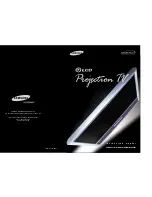
5. Use power driver or wrench, 5/16” socket, (2x) 10-32 x ⅜”
hex head screws (L) to attach the provided Lever Lock
adapter brackets (M) into the 4th and 5th openings (and
the 5th screw hole) from the bottom inside your cart
as shown. (
FIGURE J
)
6. Install Lever Lock™ channel (N) into the
adapter brackets (M).
For more information, reverse the
steps in "Removing Lever Lock™ Plate and
Channels" on page 15 of the FlexView
Conferencing Cart with HuddleSHOT FC
Instruction Sheet (100-00057).
PREPARING YOUR CART FOR POWER RETRACTOR INSTALLATION
Hex
Head
Screw
Lever Lock
Bracket
NOTE
: Hex head screw
shown in black for clarity.
FIGURE J
FIGURE H
Left
Adapter
Bracket
(M)
Right
Adapter
Bracket
(M)
1
2
3
4
5
Fifth
Screw
Hole
NOTE
:
• Attach the left and right brackets (M) into the
4th and 5th openings (and use the 5th screw
hole) from the bottom of the inside your cart.
• Brackets, 4th and 5th openings, and hole are
shown in black for clarity.