background image


18 

Settings:

  Select this icon to edit the time of day that the flush cycle will occur.  Other 

programming functions can be accessed using this icon, however, it is strongly 
recommended that you do not change any settings without first discussing with your dealer. 
 

Regeneration: 

 Select this icon to schedule a flush cycle to occur immediately or the next 

time that time of day equals the regeneration (flush) time. 
 
The touch screen has an energy-saving feature that will turn the display off (sleep mode) if 
no user input has been made for 5 minutes.  To turn the screen back on, just touch it. 
 
We will first set the time of day to the correct time.  The current day of the week and time is 
displayed in the top left corner of the home screen.  It is important that the day and time be 
accurate so that the backwash cycle will occur at the correct time of the day and so that the 
diagnostic and data gathering functions of the control valve will be accurate.   
 
If the day and time are flashing, it means that there has been a power failure and the day 
and time need to be checked. 
 
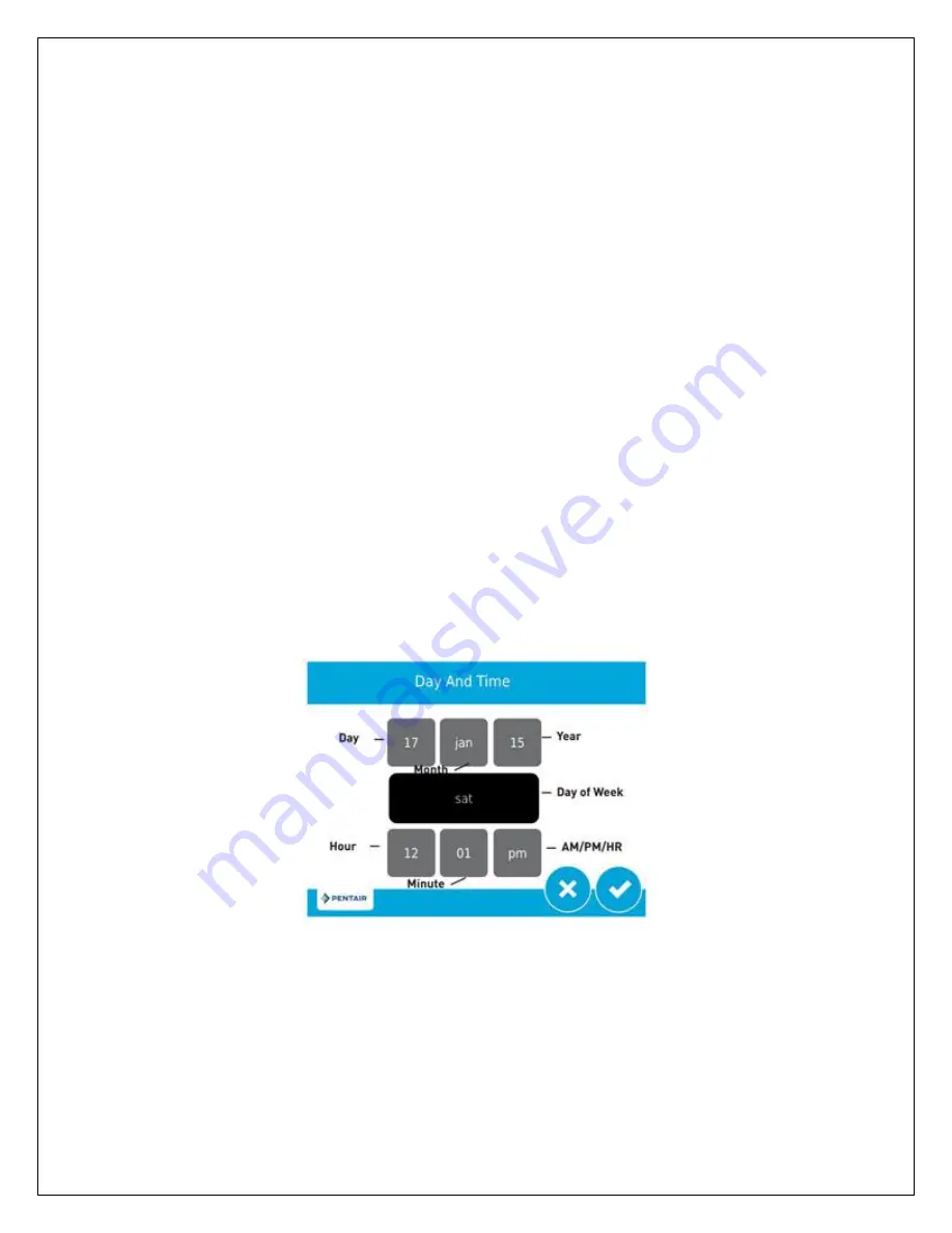
To change the time of day, touch the day and time display in the top left corner of the home 
screen and the following screen will appear: 


Touch the grey box associated with the year.  2 blue arrows will appear.  Touch the blue 
arrow on the left to decrease the year.  Touch the blue arrow on the right to increase in the 
year.  Adjust the year by touching the arrows until it is correct. 


Similarly, touch the grey boxes associated with the month and day and use the arrows to 
adjust the month and day settings until they are correct 
 

Summary of Contents for MT-5810XTR2-10-54

Page 1: ...rticulate reduction filters with higher flow rates lower backwash rates and finer filtration than the competition APPLICABLE MODELS MT 5810XTR2 Series PLEASE READ THIS MANUAL CAREFULLY BEFORE ATTEMPTING INSTALLATION FAILURE TO FOLLOW THESE INSTRUCTIONS MAY AFFECT THE PERFORMANCE OF YOUR SYSTEM VOID YOUR WARRANTY AND RESULT IN PROPERTY DAMAGE ...

Page 2: ...mpanies The Fleck 5810 control valve is well respected for its reliability serviceability simple operation and value The integrated Fleck XTR2 touch screen valve controller offers unsurpassed simplicity of operation yet complete control over all important valve operations The Fleck 5810 XTR2 Water Softener of Filter Control Valve Service Manual is also included with your system It includes additio...

Page 3: ...f the Water Electric Water Heaters 11 Step 5 Prepare and Install Inlet and Outlet Plumbing Connection 12 Step 6 Drain Line Installation 14 Step 7 Control Valve Set up 16 Step 8 Initial Start up and Leak Testing 19 BACKWASH 21 CHANGING TIME OF DAY 22 CHANGING BASIC SETTINGS 23 DIAGNOSTICS 24 MASTER SETTINGS MODE 26 OPERATION DURING A POWER FAILURE 27 MAINTENANCE TROUBLESHOOTING 28 WARRANTY INFORMAT...

Page 4: ... installed system are heavy Precautions should be taken to prevent personal injury or strain Do not move heavy components without assistance if you are not physically capable of safely carrying out the procedure If the water treatment system is to be left unattended for an extended period of time vacation etc we strongly recommend that you turn off the water supply to the system or the whole house...

Page 5: ...PSI if your water pressure is greater than 70 PSI we recommend that you have a certified plumber install a pressure reducing valve ahead of the MicroTurb system The system cannot be subjected to freezing conditions or severe damage to the system and your property could occur pH correction is strongly recommended where pH levels are less than 6 5 to prevent damage to your control valve and plumbing...

Page 6: ...HE INSTALLATION PROCESS IF IN DOUBT CALL YOUR DEALER FOR ADVICE INSTALLED UNITS CANNOT BE RETURNED INSTALLATION WE RECOMMEND THAT YOU READ THIS ENTIRE MANUAL BEFORE STARTING THE ACTUAL INSTALLATION WHILE WE STRONGLY RECOMMEND THAT A LICENSED PLUMBER PERFORM ALL INSTALLATION WORK A MECHANICALLY INCLINED HOMEOWNER WITH SUITABLE PLUMBING KNOWLEDGE CAN INSTALL THIS SYSTEM IN ALL CASES IT IS CRITICAL T...

Page 7: ...Location While exterior installation in warm climate areas is possible we strongly recommend interior installation only The system cannot be allowed to freeze or severe system damage could occur The system should not be exposed to rain and it should not be installed in direct sunlight as long term exposure to UV light could damage components of the system Furthermore direct sunlight could raise th...

Page 8: ...will also require a suitable drain to discharge waste water from the backwash cycle A drain standpipe for a washing machine floor drain or sump pump are excellent drain options We recommend that the drain line be connected to a minimum 1 drain standpipe or floor drain located ideally below the top of the head of your water filter If possible the drain should be no farther than 20 feet from the sys...

Page 9: ...stic riser tube which extends from the bottom of the tank to the top of the tank where the control valve is attached At the bottom of the tank there is a recess in the center of the tank to accept the distributor to keep it properly aligned The riser tube has been pre cut to the correct height for you When the distributor is correctly positioned the top of the riser tube will be approximately 1 8 ...

Page 10: ...2 to 3 4 full This is normal The media tank should never be filled to the top of the tank as the remaining space known as the freeboard is necessary for the media to have room to expand during the backwash cycle Once you have finished adding the media to the tank remove the tape from the distributor tube Be careful not to pull upwards on the riser tube while doing this as it is important that the ...

Page 11: ...there is no debris such as gravel or media in the tank threads Screw the control valve onto the tank Make sure that the riser tube inserts into the center hole in the upper screen and the control valve as you screw down the valve The control valve should be hand tightened clockwise Do NOT use the control valve s timer assembly for leverage and do not use tools A firm grasp with both hands at the b...

Page 12: ... COPPER PIPING FOR YOUR INSTALLATION AND WILL BE SOLDERING THE JOINTS DO NOT APPLY HEAT NEAR YOUR CONTROL VALVE BYPASS ASSEMBLY 1 NPT CONNECTOR YOKES OR THE DRAIN FITTINGS OTHERWISE SERIOUS DAMAGE TO THESE PARTS COULD OCCUR ALWAYS SOLDER JOINTS WITH THESE COMPONENTS DETACHED IF YOU ARE USING COPPER ADAPTERS TO CONNECT TO THE 1 NPT CONNECTOR YOKES IT IS RECOMMENDED THAT YOU SOLDER A 6 INCH PIECE OF...

Page 13: ...CTION The bypass assembly is secured to the control valve using threaded fittings Thread sealant tape should not be used on these threads The seal is made by way of o rings To attach the bypass to the control valve simply thread the 2 nuts on the bypass onto the valve until the nuts bottom out on the valve body Do not overtighten it is normal for some play to exist when the bypass assembly is prop...

Page 14: ...STE LINE TO PREVENT THE POSSIBILITY OF BACK SIPHONING ALWAYS FOLLOW LOCAL CODES THE DRAIN LINE SHOULD NOT BE EXPOSED TO FREEZING TEMPERATURES During the backwash cycle your MicroTurb will send captured contaminants out the drain port This port needs to be connected to a suitable household drain ideally within 20 feet of your media tank A nearby floor drain sump pump or a standpipe for a washing ma...

Page 15: ... 10 54 3 4 1 MT 5810XTR2 12 52 1 1 MT 5810XTR2 13 54 1 1 MT 5810XTR2 14 65 1 1 Polyethylene tubing PEX PVC CPVC or copper pipe are all acceptable material choices for the drain line If you are using flexible tubing be sure that there are no kinks or crimps in the tubing after installation that may cause a flow restriction If used overhead drain lines are not to exceed a height of 5 feet above the ...

Page 16: ... must be done according to local codes Plug the control valve into a standard grounded 120 volt 60 Hz electrical outlet Be certain that the outlet is uninterrupted and not controlled by a switch An extension cord may be used to reach a suitable electrical outlet Ensure that the extension cord is UL CSA certified and of an appropriate wire gauge for the application Plug the other end of the power c...

Page 17: ...r applicable cycles in black The bottom menu bar provides the following options Vacation Select this icon to set your water filter system to vacation mode This mode can be used if you will be away for an extended period of time and will not be using water When vacation mode is selected the system will temporarily cease flush cycles Upon returning from vacation it is important to remember to end th...

Page 18: ...e top left corner of the home screen It is important that the day and time be accurate so that the backwash cycle will occur at the correct time of the day and so that the diagnostic and data gathering functions of the control valve will be accurate If the day and time are flashing it means that there has been a power failure and the day and time need to be checked To change the time of day touch ...

Page 19: ...they are not set to regenerate at the same time We recommend that they backwash regenerate at least 2 hours apart Follow the instructions under Changing Basic Settings to change the frequency or backwash time if desired If you want to change the duration of the backwash or final rinse cycles these settings must be edited in the Master Settings Mode see below for details Step 8 Initial Start up and...

Page 20: ...vice mode INSPECT YOUR DRAIN LINE PLUMBING CONNECTIONS AND REPAIR ANY LEAKS IMMEDIATELY BEFORE PROCEEDING IF THE PLUMBING PIPE RATTLED OR VIBRATED DURING THIS PROCESS CAUSING EXCESSIVE NOISE USE ADDITIONAL FASTENERS TO BETTER SECURE THE DRAIN LINE Touch the REGENERATION ICON You will be given a choice to regenerate now or at regen time select now to engage a full backwash and rinse cycle Allow the...

Page 21: ...ten discolored or has evidence of sediment increase the duration of the rapid rinse cycle in 1 minute increments until the problem is resolved During each step of backwash the touch screen display on the control valve will indicate the cycle currently underway regeneration wheel and the amount of time remaining in that cycle top right corner There may be instances where more frequent backwash is r...

Page 22: ... corner of the home screen It is important that the day and time be accurate so that the flush cycle s will occur at the correct time of the day and so that the diagnostic and data gathering functions of the control valve will be accurate If the day and time are flashing it means that there has been a power failure and the day and time need to be checked To change the time of day touch the day and...

Page 23: ...lso adjust the brightness of the touch screen display To enter the Settings Mode touch the SETTINGS ICON in the main menu at the bottom of the home screen The following screen will appear Day Override The default setting is 5 days There may be instances where more frequent backwash is required For instance if your water consumption increases considerably or if your feed water conditions temporaril...

Page 24: ...will change accordingly When you are satisfied with the brightness level press the CHECKMARK ICON in the bottom right corner of the screen To cancel your changes and return to the home screen press the X ICON at any time Master Settings The Master Settings Mode allows service technicians to set up the valve for optimal performance A password is required to enter this mode We do not recommend that ...

Page 25: ...talizer meter touch totalizer and then select the icon in the bottom right corner of the next screen The totalizer meter will be reset to zero The second screen displays when the last regeneration flush cycle occurred as well as the software version that is used by your control valve The third screen indicates the number of flush cycles that the valve has done as well as the average interval betwe...

Page 26: ...s Mode select the SETTINGS ICON from the home screen then select the SETTINGS ICON again The password is 1201 The following settings are the factory default settings FORMAT Parameter Setting language english units us hardness units gpG VALVE Parameter Setting system 4 valve 5810 regen type filter mtr delayed day override time driven 5 regen time 12 30 am vol override volumetric 2000 G REGEN Parame...

Page 27: ... on OPERATION DURING A POWER FAILURE The 5810XTR2 valve controller includes integral power backup In the event of power failure the control shifts into a power saving mode The display and motor shut down but it continues to keep track of the time and day for a minimum of 48 hours The system configuration settings are stored in a non volatile memory and are stored indefinitely with or without line ...

Page 28: ...s originally scheduled THE DRAIN LINE PLUMBING CONFIGURATION SHOULD INCLUDE ALL REQUIRED SAFETY COMPONENTS TO PREVENT OVERFLOWS RESULTING FROM A POWER FAILURE DURING REGENERATION MAINTENANCE TROUBLESHOOTING THE CONTROLLER MUST BE DEPRESSURIZED BEFORE REMOVING ANY QUICK CONNECTION CLIPS OR THE VALVE ITSELF FOR SERVICING THE CONNECTOR SHOULD BE PUSHED TOWARD THE CONTROL VALVE WHILE REMOVING CLIPS Se...

Page 29: ...your treatment tank 4 Water running to drain during service mode A Internal valve leak B Jammed piston A Replace seals and spacers and or piston B Remove obstruction debris and inspect seals and spacers and or piston for damage 5 Cloudy water and or poor water pressure after initial installation A Additional backwash required A Perform 1 or more additional manual backwash cycles WARRANTY INFORMATI...

Page 30: ...roduct s was were originally installed Only products purchased from an Authorized Dealer or HomePlus Products Inc directly are eligible for this warranty The products must have been installed and operated in accordance with the instructions and operating conditions stated in the Owner s Manual Customer must register his or her warranty with HomePlus products Inc within 90 days of original purchase...

Page 31: ...ies are in lieu of any other warranty whether expressed or implied written or oral including any warranty of merchantability or fitness for a particular purpose HomePlus Product Inc s liability arising out of the manufacture sale or supplying of the products or their use or disposition whether based upon warranty contract tort or otherwise shall not exceed the actual purchase price paid by the aut...

Page 32: ...32 MANUFACTURED BY HomePlus Products Inc 5 1490 Pearson Place Kamloops BC V1S 1J9 Canada Phone 250 374 2690 Fax 250 374 2692 www homeplusproducts com ...

Reviews: