background image

ScanMaker i900 Installing and Getting Started     7

Connecting the Scanner to Your Computer

The ScanMaker i900 comes with both FireWire and Hi-Speed USB built-in
interfaces. You may choose either FireWire (IEEE-1394) or Hi-Speed USB as the
interface for connection between the scanner and computer. (You can use only one
interface at a time.)

Using the FireWire Cable

Check first to see if your computer system is FireWire-ready. For Macintosh users,
make sure your Macintosh is equipped with a built-in FireWire port. For PC users,
install the FireWire card first (provided with your scanner package) before
connecting  the scanner and your PC.  For more details on how to install the FireWire
card, refer to the documentation that come with your scanner package or your
purchased FireWire card.

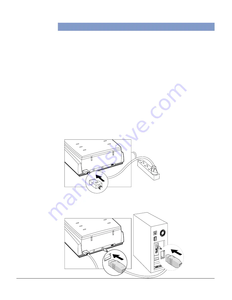
Follow the steps below to perform the FireWire connection.

1. Plug the power cord into the back of the scanner, and plug the other end into a

power source (power surge protector highly recommended).

Note

:  Make sure no other

cable is connected to the
scanner except the power cord
at this point.

2. Connect one end of the FireWire cable to your computer, and connect the other

end of the cable to the scanner’s FireWire port.

For PC users

(with a

FireWire card

installed)

Summary of Contents for ScanMaker i900

Page 1: ...n 18 A Scanning Regular Non Damaged Photos 18 B Scanning Damaged Photos 19 C ScanningTransparent Film 21 Specifications 22 Federal Communications Commission Interference Statement 23 Trademarks Microt...

Page 2: ...IGITAL ICETM for Photo Prints Technology and ColoRescueTM DIGITAL ICE for Photo Prints Technology automatically maps identifies and eliminates surface defects on your photos Built into the hardware an...

Page 3: ...necessary for scanner setup If there are any damaged or missing parts contact Microtek s customer service department 1 ScanMaker i900 scanner 2 1 FireWire card 2 2 FireWire cable 2 3 USB 2 0 cable ba...

Page 4: ...g a closer look Power connector Accessory port FireWire port 1 USB 2 0 port 1 Horizontal ruler Scanner lid Glass surface Upper scan bed Vertical ruler Power button Power indicator green Reflective Rea...

Page 5: ...g slightly from the bottom of the scanner Shipping the Scanner If you have to transport the scanner the scanner must be locked To lock the scanner follow the steps below 1 Turn off the scanner if your...

Page 6: ...on a separate CD ROM included in your scanner package 6 Restart your computer For Macintosh Users 1 Turn on your computer 2 Install the image editing software application which is on a separate CD ROM...

Page 7: ...install the FireWire card first provided with your scanner package before connecting the scanner and your PC For more details on how to install the FireWire card refer to the documentation that come...

Page 8: ...ent connect the Hi Speed cable to the Hi Speed USB port not to the USB 1 1 port to obtain faster scanning If your computer does not have a Hi Speed USB port install a Hi Speed USB card to make use of...

Page 9: ...e to the scanner s USB port 3 Press the power button on the front panel of the scanner and wait for the lights to stop blinking and stay on steady The scanner will be detected by your system automatic...

Page 10: ...eflective materials such as photos and prints 1 Open the scanner lid 2 Place the original to be scanned face down on the scanner s glass surface Center the top of the original along the horizontal rul...

Page 11: ...is used together with the individual holders to scan a particular type of standard sized transparent film such as individual 35mm slides 35mm filmstrips 120 film or 4 x 5 film Calibration slit Glass H...

Page 12: ...older 2 Place the vinyl strip on the edges of the transparency to secure the film in place 3 Insert the holder all the way into the transparency bay the drawer or lower compartment of the scanner Note...

Page 13: ...m holders together with the Main Holder for scanning a particular type of standard sized film For instance use the 4 x 5 film holder to scan 4 x 5 film or use the 35mm filmstrip holder to scan 35mm fi...

Page 14: ...into the holder 2 Place the slide holder in the Main Holder 3 Insert the whole assembly into the transparency bay the drawer or lower compartment of the scanner B Using the 35mm Filmstrip Holder Two...

Page 15: ...der should match the filmstrip s frame by frame partitions Frame by frame partition 2 Put the filmstrip holder into the Main Holder 3 Insert the whole assembly into the transparency bay the drawer or...

Page 16: ...t film sizes of transparencies including 6 x 4 5 cm 6 x 6 cm 6 x 7 cm and 6 x 9 cm 1 Place the film into the holder a Push on the side to open the lid b Place the film in the holder c Pull down the si...

Page 17: ...s of 4 x 5 film at a time 1 Place the film into the holder a Push on the side to open the lid b Place the film in the holder c Pull down the side to close the lid 2 Put the film holder into the transp...

Page 18: ...ndow you can resize the scan frame floating dotted line around the image by dragging on the edge or corner of the scan frame to determine the final size of the actual scan 4 Click the Original button...

Page 19: ...anned face down on the scanner glass surface Center the top of the photo along the horizontal ruler on the scanner Note If the creases lie in the same direction where the carriage is moving the crease...

Page 20: ...ngs window should be None Otherwise the DIGITAL ICE option in the next step will be dimmed and will not be available for selection 7 Choose the DIGITAL ICE option that works best for you Select from N...

Page 21: ...e image 6 In the preview window you can resize the scan frame floating dotted line around the image by dragging on the edge or corner of the scan frame to determine the final size of the actual scan 7...

Page 22: ...ution Optical 6400 dpi x 3200 dpi Interpolated 25 600 dpi x 25 600 dpi Interface Hi Speed USB USB 2 0 and FireWire IEEE 1394 standard Dimensions L x W x H 23 6 x 15 2 x 6 3 600 mm x 386 mm x 160 mm We...

Page 23: ...e by one or more of the following measures Reorient or relocate the receiving antenna Increase the separation between the equipment and receiver Connect the equipment into an outlet on a circuit diffe...

Reviews: