background image

14 

The Xpress XL Desktop

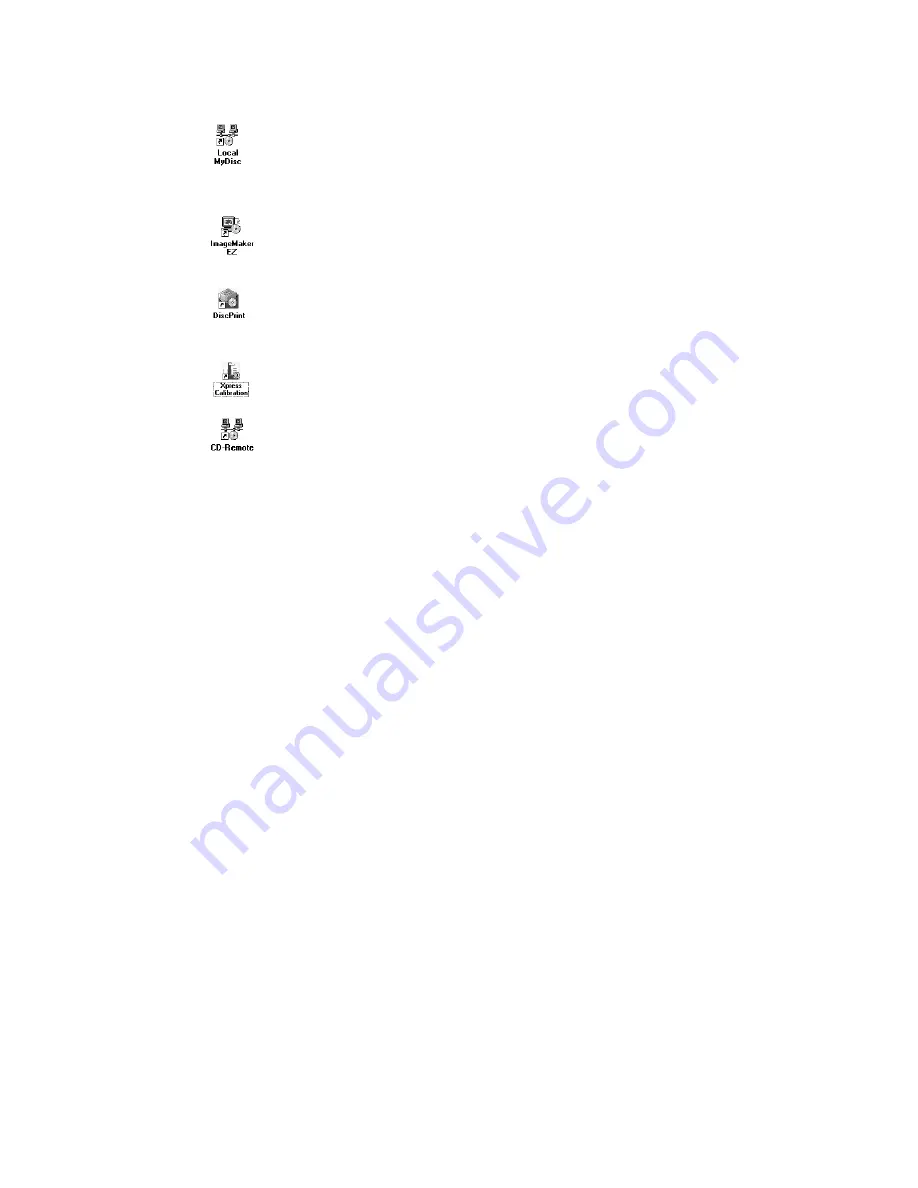
Important icons and other parts of the desktop

MyDisc icon

Starts the standard MyDisc program used to create master images of custom discs 

from which to make copies. Using MyDisc for making discs is covered in the software 

manual.

ImageMaker EZ icon

Starts the disc duplication program used to make disc copies. Instructions for using 

ImageMaker EZ  are covered in the software manual. 

DiscPrint icon

Starts the DiscPrint program, the “stand-alone” version of the ImageMaker EZ disc 

layout editor, used to create and modify disc printing layouts.

Xpress XL Calibration icon

Starts the Xpress XL calibration utility used for calibrating the system.

CD-Remote icon

Starts the 

CD-Remote

 background process and is only necessary should you need to 

restart the process. 

CD-Remote

 starts automatically when it is needed. 

Windows taskbar

When a program is started (e.g. MyDisc), a button for that program will appear in 

the taskbar (located at the bottom of the desktop screen). If a program has been 

minimized (still running, but not displayed on screen), or if it has disappeared behind 

another program’s window, clicking its taskbar button will make it appear on screen.

Summary of Contents for Xpress XL

Page 1: ...Xpress XL Disc Production System Hardware Manual Revision 3 003 0085 03 ...

Page 2: ......

Page 3: ...on Workspace 5 Checking Your Shipment 6 Unpacking Xpress XL 6 Xpress XL Contents 7 Xpress XL Assembly Procedures 8 Operation 11 Powering Up the Xpress XL 11 The Xpress XL Desktop 12 Checking the Xpress XL Software Configuration 13 Calibrating Xpress XL 15 Placing Discs on Spindles 18 Shutting Down Xpress XL 18 Maintenance 19 Microtech Support 19 ...

Page 4: ......

Page 5: ...gulations 1 This device may not cause harmful interference and 2 this device must accept any interference received including interference that may cause unde sired operation NoticeforEurope EuropeanStandards This equipment conforms to the EMC Directive 89 336 EEC by compliance with the following European standards EN 55022 1998 A1 2000 CISPR 22 1997 A1 2000 Emissions EN 50024 1998 A1 2001 CISPR 24...

Page 6: ... ...

Page 7: ...erred to later in the manual take a few moments to become familiar with them The main parts of the Xpress XL production system are indicated below front view Reject Spindle R 6 Disc Writers Spindle 5 Spindle 4 Spindle 3 Spindle 2 Spindle 1 Switch Panel Printer 2 Printer Plate 6 Disc Writers Drive Encosure Handholds Printer 1 Digital Camera ImageAligner 2 Light Shield Camera Mount Elevator Arm Hois...

Page 8: ...t ers installed from 1 to 4 depends on your particular system Writers can be CD R DVD R or a mix The PC module contains the entire PC including disc readers hard disk and power supply The disc reader reads master discs to be duplicated and other tasks The disc reader drive is a DVD ROM drive The disc spindles hold discs in various stages of processing There are five full height spindles for holdin...

Page 9: ...ure that the power receptacles are properly grounded The average power require ment for the entire system is 250 watts The peak requirement may reach 400 watts Microtech recommends using a surge protector and or power conditioner for optimal setup Adequatelighting There should be enough light both for operating the equipment and for examining the discs you produce and print In addition if the Imag...

Page 10: ...ys tem If the shipping cartons are present and not damaged start setting up a workspace for your production system Unpacking Xpress XL There are five basic Xpress XL configurations 1 Basic system only no printer 2 Basic system with 2 XpressJet inkjet printers 3 Basic system with 2 Perfect Image thermal transfer printers 4 Basic system with the 2 Perfect Image thermal transfer printers and ImageAli...

Page 11: ...s Box 6 Monitor Box 7Printer w cables Box 8 optional2nd printer Printer w cables Box 9 10 identicalcontentsineachbox optionalImageAlilgnerIICameras Digital Camera Camera Support Boom Light Shield Camera Mount Disk Thumbscrews 3 Male and 1 Female Camera Cable Calibration Disc During unpacking visually inspect parts for dents scratches or other damage If any parts are damaged call Microtech s Custom...

Page 12: ...losure Cabling 1 Drive enclosure ATX 24 pin power cable connects to back of elevator 2 Connect power from lower power supply to back of elevator to right of the ATX connector 3 Connect three ribbon cables and two black AUX cables located underneath fans on right to their respective connectors on back of elevator Each connector is unique and will only fit one receptacle 4 Connect Drive Cables 12 Ca...

Page 13: ...ack of Xpress XL base unit 3 Connect printer power cord to port on back of printer plug opposite end into standard electrical outlet Perfect Image Left Side 1 Connect the light grey serial cable with USB adapter between port on back of printer to USB port COM3 on back of Xpress XL base unit 2 Connect USB cable between port on back of printer to USB port on back of Xpress XL base unit 3 Connect pri...

Page 14: ...mera Support Boom on top of Printer Base Plate behind Elevator 2 Tighten attached knobs 3 to secure Camera Support Boom to threaded holes in Printer Base Plate 3 Line up pegs 2 and threaded rod on top of Light Shield Camera Mount Disk with holes on bottom of camera support boom 4 Finger tighten knob onto threaded rod to secure Light Shield Camera Mount Disk to Camera Support Boom 5 Attach Camera t...

Page 15: ... working correctly close the configuration program 1 Start the Xpress calibration utility Start Programs ImageMaker Xpress Calibration Make sure that both printers are properly configured If either printer is grayed out then check its control connection For a Rimage printer this means check the serial port setting via the configuration program For all other printers make sure that the control cabl...

Page 16: ...12 ...

Page 17: ... control panel on the front of system Xpress XL is a Microsoft Windows based system Upon powering up the system for the first time Windows will ask you for some general system set up informa tion including an agreement to licensing terms your time zone computer name password and network preferences You will also be asked to validate Windows by entering the Product Key which is located on the back ...

Page 18: ...ImageMaker EZ disc layout editor used to create and modify disc printing layouts XpressXLCalibrationicon Starts the Xpress XL calibration utility used for calibrating the system CD Remoteicon Starts the CD Remote background process and is only necessary should you need to restart the process CD Remote starts automatically when it is needed Windowstaskbar When a program is started e g MyDisc a butt...

Page 19: ...on the lower left corner of the desktop From the menu that pops up work through the submenus to select Programs ImageMaker Configure ImageMaker The configuration dialog shown below will open Check the following configuration items to make sure they re set correctly Ifaprinterisinstalled itmustbeidentifiedintheprintersettingsandoptions Select the printer names and position on the Xpress XL left or ...

Page 20: ...er Left and the other is called Rimage Perfect Image Printer Right Left is COM3 and Right is COM1 To test either printer place the disc on the printer tray and click Test button for corresponding printer The printer will print the word test on the disc If it does not check the cabling on the printer and the port settings in printer driver If no printer is installed at any position left or right yo...

Page 21: ...librations Click the Calibrate Position button and click on the button for the spindle you wish to calibrate S1 for example The disc transport arm will move over to the top of the spindle move down close to the top of the spindle and then stop If the arm is not centered exactly over the spindle the calibration of the spindle must be corrected Use the two arrow buttons and to bump the position of t...

Page 22: ...tside clamping pins XpressJet Center the disc so that it is about 1 8 3 4mm away from each of the two front stationary pins TEACP 55 Center the disc so that two left stationary pins are close to but not touching the center of the disc FORALLPRINTERS To make left right adjustments loosen the four screws on the printer plate and slide the printer left or right as necessary Then tighten the screws wh...

Page 23: ...talled the disc will be picked up from the disc writer drive tray and dropped on spindle 5 Observethefollowingcarefullyduringtest Arm centers on spindle Disc is dropped in center of drive writer tray Disc is dropped onto output spindle IfPrinterisinstalled Disc is dropped in center of printer tray Printer is able to clamp the disc If the continuous test fails at any point during the cycle repeat t...

Page 24: ...k discs will be retrieved from spindle 4 and completed discs will be placed on spindle 5 When all discs have been removed from spindle 3 the whole operation will shift to the left by one spindle and blank discs will be retrieved from spindle 3 and completed discs will be placed on the now empty spindle 4 When all 800 discs have completed there will be discs on spindles 2 thru 5 and nothing on spin...

Page 25: ... the tightness of the thumbscrews that hold the main assemblies together If none of these solutions solve the problem please have the following informa tion available before calling Microtech Systems support 1 Serial number 4 digit number located on the back of the system or under the keyboard 2 Detailed description of problem s experienced Microtech Systems 2 Davis Drive Belmont CA 94002 650 596 ...

Page 26: ......

Page 27: ... Software Configuration 12 Installation Set Up 5 Installing ImageAligner 10 Placing Discs on Spindles 18 Power Up Xpress XL 11 Printer Connections 9 Shutting Down Xpress XL 18 Software Configuration 13 System Parts 3 System Specifications 4 Xpress XL Desktop 11 ...

Reviews: