Troubleshooting
Symptom
Corrective Steps
Extender
does not
power up
1. Verify that the input port of the
PoE extender is connected to an
active IEEE 803.af/at PSE
equipment.
The PD
does not
operate
1. Verify that the extender is
powered up.
2. Verify that the Extender detects a
PD.
3. Verify that the PD is designed for
IEEE 802.3 af/at operation.
4. Verify that you are using a
standard Category 5/5e/6, straight-
wired cable, with four pairs.
5. If an external power splitter is in
use, replace it with a known, good
splitter.
6. Verify that the PD is connected
to the Data & Power output port.
7. Try to reconnect the same PD
into a different Extender. If it works,
there is probably a faulty port or
RJ45 connection.
8. Verify that there is no short over
any of the twisted pair cables or
over the RJ45 connectors.
The end
device
operates,
but there
is no data
link
1. Verify that for this link, you are
using standard UTP/FTP Category
5/5e/6 straight (non-crossover)
cabling, with all four pairs.
2. Verify that the Ethernet cable
length is less than 100 meters from
the Ethernet source to the
load/remote terminal.
3. Try to reconnect the same PD
into a different Extender. If it works,
there is probably a faulty port or
RJ45 connection.
4. If an external power splitter is in
use, replace it with a known-good
splitter.
Indicators
Power LEDs
LED Color and
Status
PoE Input Status
PoE Output Status
Green ON
PoE input power
enabled
PoE output power
enabled
Green OFF
PoE input power
disabled
PoE output power
disabled
Network LEDs
LED Color and
Status
Network Input/Output Status
Orange ON
Network connection
Orange OFF
No network connection
Orange Blinks –
12 Hz rate
10/100/1000 Mbps communication data
rate
Specifications
Environmental Specifications
Mode
Temperature
Humidity
Operating
1 G data rate
0 to 40°C
32 to 104°F
10 to 90%
(no condensation
allowed)
Operating
10/100 M data rate
0 to 50° C
32 to 122°F
10 to 90%
(no condensation
allowed)
Storage
-20 to 70°C
-4 to 158°F
10 to 90%
(no condensation
allowed)
Electrical Specifications
Input Voltage
46 - 57 VDC
Maximal Input Current
0.7 Ampere
Output Voltage
44 - 55 VDC
Maximal Output Current
0.6 Ampere
Ethernet Interface
Input (Data & power In):
Ethernet 10/100/1000Base-T
RJ45 female socket
Output (Data & power In):
Ethernet 10/100/1000Base-T
RJ45 female socket
5B
WARNING
♦
Read the installation instructions before connecting
the PoE Extender to the PSE.
♦
A voltage mismatch can cause equipment damage
and may pose a fire hazard. If the voltage indicated on the
label is different from the power outlet voltage, do not
connect the PoE Extender to the power outlet.
♦
The unit is indoor rated.
6B
Preliminary Steps
♦
The PoE Extender can be placed on a rack, wall or
desktop.
Before placing the PoE Extender:
♦
Do not cover the PoE Extender. Keep the PoE Extender
away from excessive heat and humidity and free from
vibration.
♦
Use a splitter if desired; ensure that the splitter is
connected close to the PD terminal and not on the
Extender.
♦
No “on-off” switch exists; simply plug the Cat5e
Ethernet cable from the PSE device (PoE switch or
Midspan) to the Extender PoE input (RJ45 connector).
♦
Extender PoE output (the RJ45 connector) should be
connected to the PD terminal using a Cat5e Ethernet
cable.
7B
Installing the Unit
1. Connect the PoE input port to a PSE (Midspan or Switch).
2. Connect the PoE output port to a PD (IP Phone, WLAN AP,
IP Camera, and so on).
3. Verify that the unit LEDs are on.
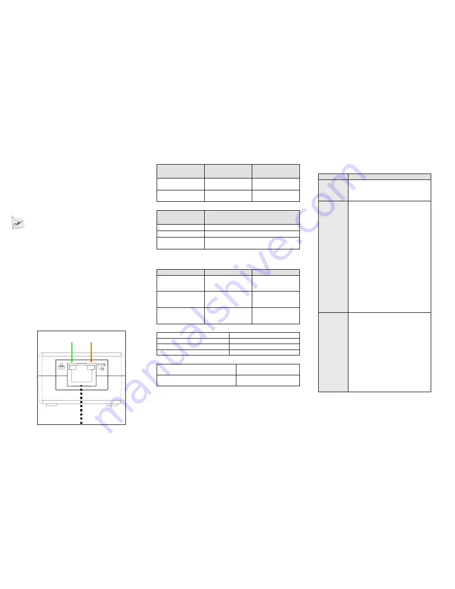
Power
LED
Network
LED
PoE + Data
Cat 5 Cable
Figure 3: Connecting the PoE Extender


