


Introduction
Thank you for purchasing Micronet SP624R 10/100 Mbps Switch. Before you start installing the
Switch, verify the following items in the package
●
SP624R 10/100 Mbps EtherFast Switch
●
Power Cord
●
Accessories pack
●
User’s Guide
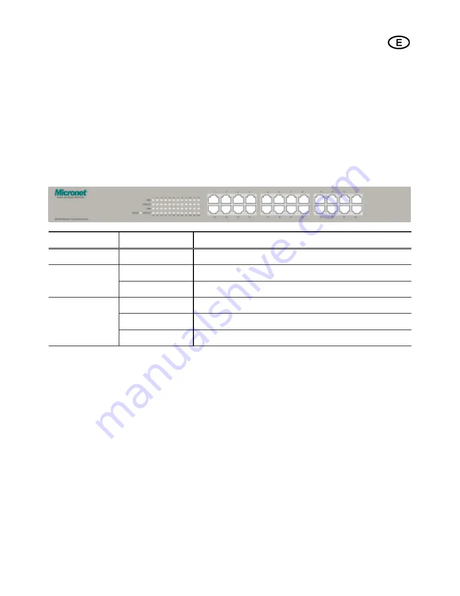
LED Indication
Please refer to the following table for LED indication of SP624R
.
LED
Status
Indication
POWER
Steady Green
The Power is on
Steady Green
The port is operating at 100Mbps
100M
Off
The port is operating at 10Mbps or there is no link
Steady Green
A valid physical UTP/STP connection exists on that port
Blink Green
The port is transmitting data
LINK/ ACT
Off
The network port is not connected
Connecting Stations
Micronet SP624R Switches do not require software configuration. Users can immediately use any of
the features of this product simply by attaching the cables and turning on the power.
Connect the RJ-45 plug to the switch. Then plug the RJ-45 on the other end of the cable into the
network adapter on the station. If the switch was powered up when you made the connection, the
LINK/ACT LEDs for all the above stations should be on.
Interconnecting Switches
In order to increase the connectivity of your network, you can connect two switches together. The
SP624R equipes Auto-Uplink (Auto MDI/MDI-X) function which could adjust RJ-45 connector's
TX and RX pin assignment automatically. With Auto-Uplink function provided for all ports on the


