Long Gage Strain Sensor |
os3610
C o p y r i g h t © 2 0 1 2 M i c r o n O p t i c s , I n c .
o s 3 6 1 0 I n s t a l l a t i o n G u i d e , R e v i s i o n A
2
Introduction:
The os3610 Surface Mount Strain Sensor measures average strain over the length of the sensor
while providing integrated temperature compensation. It is based on fiber Bragg grating (FBG)
technology. The os3610 is intended exclusively for surface mounting. Each end of an os3610 is
attached to a structure via rigid brackets that are either welded, bolted, epoxied, or grouted to the
surface of a concrete, rock, steel, composite, or other structure. The os3610 strain sensor
measures the relative movement of the two mounting brackets along the axis of the sensor. It is
important that the mounting brackets be securely attached to the surface to be tested if accurate
results are to be obtained. Several installation tools are available from Micron Optics to aid in
installation. Note that tools are available for Grout-in and Bolt-on applications of gage length
25.4 cm and 100 cm.
Installation Tools:
Grout-in Drill Guide (25.4 cm)
Grout-in Drill Guide (100 cm)
Bolt-on Drill Guide (25.4 cm)
Bolt-on Drill Guide (100 cm)
Setting Bar (25.4 cm)
Setting Bar (100 cm)
Mounting To Steel (Weldable Brackets):
The first step in installing the os3610 strain sensor is welding the two mounting brackets to the
surface to be measured. The end brackets are made of 316 stainless steel. Each mounting bracket
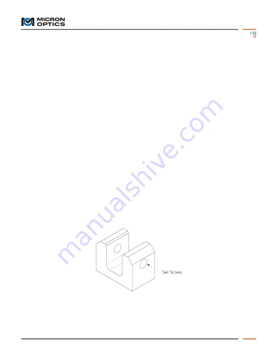
has two ¼-20 set screws installed as shown in Figure 1. Use a 1/8 inch Hex-Key to tighten set
screws.
Figure 1
– Mounting Bracket
It is important that mounting brackets are properly spaced and axially aligned prior to welding. If
axial alignment is not maintained, the sensor may bind leading to reduced sensor accuracy. The
setting bar shown in Figure 2 is used to hold the mounting brackets in alignment and properly


