background image


X249   


L3 Service Manual 


3-1-2. SIM troubleshooting


Troubleshooting flow chart


Main related component:

BBIC(U201),SIM connector(J702) 


Summary of Contents for X249

Page 1: ...ng must be undertaken by qualified personnel only II Ensure all work is carried out at an anti static workstation and that an anti static wrist strap is worn III Use only approved Tools components as specified in the parts list IV Ensure all components modules screws and insulators are correctly re fitted after servicing and alignment V Ensure all cables and wires are repositioned correctly if Han...

Page 2: ...X249 L3 Service Manual 2 L3 Service Manual V1 0 Documents statement This document is intended for use by qualified service ...

Page 3: ...X249 L3 Service Manual 3 personnel only The documents only are used for service reference TABLE OF CONTENT Sectionpage 1 Product Figures 6 1 1 Exploded view 6 ...

Page 4: ...p troubleshooting 12 3 1 2 SIM troubleshooting 14 3 1 3T Flash troubleshooting 17 3 1 4 MIC troubleshooting 16 3 1 5 Speaker troubleshooting 18 3 1 6 Earpiece troubleshooting 21 3 1 7 Vibra troubleshooting 23 3 1 8 Camera troubleshooting 25 3 1 9 FM radio troubleshooting 26 3 1 10 Display troubleshooting 28 3 1 11 Bluetooth troubleshooting 30 3 1 12 Keyboard troubleshooting 31 3 1 13 Charge troubl...

Page 5: ...rvice Manual 5 3 2 2 DCS GSM TX Part 36 4 Main Element Specifications 38 4 1 Baseband part 38 4 1 1 BBIC U201 39 4 2 RF part 46 4 2 1 RF PA U102 46 5 Test Instructions 48 6 Glossary 49 7 Warnings and cautions 52 ...

Page 6: ...oes not boo crashes U103 26MCrystals Damage caused by failure Can not boot J604USB connector Damage caused by failure Not charging data transfer faults U102 RF PA Damage caused by failure Call fault J802SIM T flash card Damage caused by failure SIM card does not know does not know the T flash card J602Headphone Jack Damage caused by failure Headphones silent not receive FM ...

Page 7: ...ULITY 1 HQ11100139000 MT6260DA 1 2 HQ11160028000 AW5007STR 1 3 HQ11160059000 AP5200 R95MOGH0 1 J604 LCD pad Damage caused by failure Does not display Keypad Damage caused by failure Invalid keys J702 cameraPAD Damage caused by failure Camera does not work ...

Page 8: ...rvice Manual 1 2 Product Main Function SupportCamera Music player Support T Flash card 2 4 QVGA LCD Support dual SIM card Support GSM900 DCS1800Network Support bluetooth Support FM radio 1 3 General Specification ...

Page 9: ...N USB DM DP URAT TX RX ANT RF_Switc h MT6260 U201 Charger IC Battery 5PIN USB J1102 3 5MM Earphoen Jack FM Radio Camera Speaker WVGA LCD SIM 1 SIM 2 Receiver GPS IC Bluetooth IC ROM RA M T FLASH Audio_PA RF_Switch RF PA RF TR Side Health RX Filter WIFI IC TX PA MI C 26M ...

Page 10: ...X249 L3 Service Manual 2 1 1 BBIC Diagrams Application Diagram of MT6260 ...

Page 11: ...X249 L3 Service Manual 2 2 Power Management Diagrams ...

Page 12: ...for acknowledgement To successfully power on the handset PWRKEY should be kept low until PMU receives the PWRBB from BB Besides the system reset ends at the moment when the Vcore Va Vio Vmare fully turned on to ensure the correct timing and function If the RTC module is scheduled to wakeup the handset at some time the PWRBB signal will directly control the PMU In this case PWRBB becomes high at th...

Page 13: ...ain related component BBIC U201 XTAL CRYSTAL U103 MINI USB J701 J1102 Check the clock generation circuit related to BBIC Check the baseband circuit related to BBIC keypadFPC LCD Check the VBAT circuit component related to U201 LCD keypadbacklight VIB ...

Page 14: ...X249 L3 Service Manual 3 1 2 SIM troubleshooting Troubleshooting flow chart Main related component BBIC U201 SIM connector J702 ...

Page 15: ...X249 L3 Service Manual 3 1 3 T Flash troubleshooting Troubleshooting flow chart Main related component BBIC U201T FLASH CONNECTOR J702 J702 ...

Page 16: ...X249 L3 Service Manual SIM CIRCUIT T Flash circuit m BBIC SIM1 rom BBIC T card From BBIC SIM2 ...

Page 17: ...X249 L3 Service Manual 3 1 4 MIC troubleshooting Troubleshooting flow chart Main related component BBIC U201MIC ...

Page 18: ...X249 L3 Service Manual MIC circuit To BBIC From MIC ...

Page 19: ...X249 L3 Service Manual 3 1 5 Speaker troubleshooting Speaker circuit FROM BBIC To Speaker ...

Page 20: ...X249 L3 Service Manual Troubleshooting flow chart Main related component BBIC U201 SPEAKER ...

Page 21: ...X249 L3 Service Manual 3 1 6 Earpiece troubleshooting Troubleshooting flow chart Main related component BBIC U201EARPIECE ...

Page 22: ...X249 L3 Service Manual Earpiece circuit To earpiece FROM BBIC ...

Page 23: ...X249 L3 Service Manual 3 1 7 Vibra troubleshooting Troubleshooting flow chart Main related component BBIC MOTOR ...

Page 24: ...X249 L3 Service Manual Vibra circuit To VIB ...

Page 25: ...X249 L3 Service Manual 3 1 8 Camera troubleshooting Troubleshooting flow chart Main related component BBIC U201 CAMERA MODULE ...

Page 26: ...X249 L3 Service Manual Camera circuit From BBIC ...

Page 27: ...3 Service Manual 3 1 9 FM radio troubleshooting Troubleshooting flow chart Main related component BBIC U201earphone jack J602 Check earphone jcak J602 solder joints and spring contacts Are those OK U201 U201 ...

Page 28: ...X249 L3 Service Manual FM Circuit From earphone HEADGND ANT IN ...

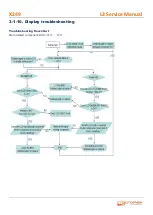
Page 29: ...X249 L3 Service Manual 3 1 10 Display troubleshooting Troubleshooting flow chart Main related component BBIC U201 LCD ...

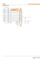
Page 30: ...X249 L3 Service Manual Display Circuit ...

Page 31: ...X249 L3 Service Manual 3 1 11 Bluetooth troubleshooting Troubleshooting flow chart Main related component BBIC U201 Bluetooth circuit ...

Page 32: ...X249 L3 Service Manual 3 1 12 Side health Troubleshooting Keyboard circuit ...

Page 33: ...X249 L3 Service Manual Troubleshooting flow chart Main related component BBIC U201 and keypad FPC ...

Page 34: ...X249 L3 Service Manual 3 1 13 Charge troubleshooting Troubleshooting flow chart Main related component BBIC U201 MINI USB J701 charge U301 ...

Page 35: ...X249 L3 Service Manual Battery charge circuit Charge control Charge 5V in ...

Page 36: ...X249 L3 Service Manual 3 2 RF 3 2 1 GSM DCS RX troubleshooting Troubleshooting flow chart Main related component BBIC U201 XTAL CRYSTAL U103 RF PA U102 ...

Page 37: ...X249 L3 Service Manual 3 2 2 GSM DCS TX Part Troubleshooting flow chart Main related component BBIC U201 XTAL CRYSTAL U103 RF PA U102 ...

Page 38: ...X249 L3 Service Manual RF Circuit RF PA circuit TX RX ...

Page 39: ...X249 L3 Service Manual 4 Main Element Specifications 4 1 Baseband part 4 1 1 BBIC U201 ...

Page 40: ...X249 L3 Service Manual ...

Page 41: ...X249 L3 Service Manual ...

Page 42: ...X249 L3 Service Manual ...

Page 43: ...X249 L3 Service Manual ...

Page 44: ...X249 L3 Service Manual ...

Page 45: ...X249 L3 Service Manual ...

Page 46: ...X249 L3 Service Manual ...

Page 47: ...X249 L3 Service Manual 4 2 RF part 4 2 1 RF PA U102 ...

Page 48: ...X249 L3 Service Manual ...

Page 49: ...nd 510838 into the automatic test mode 1 Version test 2 LCD test 3 LCD BcakLight test 4 KeyPad test 5 MIC Receiver test 6 Headset test 7 FM Radio test 8 Back Camera test 9 ADC Charger test 10 Battery Charge test 11 SIM detect test 12 BlueTooth test 13 RTC test ...

Page 50: ...X249 L3 Service Manual 6 Glossary ...

Page 51: ...X249 L3 Service Manual ...

Page 52: ...rvicing and alignment must be undertaken by qualified personnel only Ensure all work is carried out at an anti static workstation and that an anti static wrist strap is worn Ensure solder wire or foreign matter does not enter the telephone as damage may result Use only approved components as specified in the parts list Ensure all components modules screws and insulators are correctly re fitted aft...

Reviews: