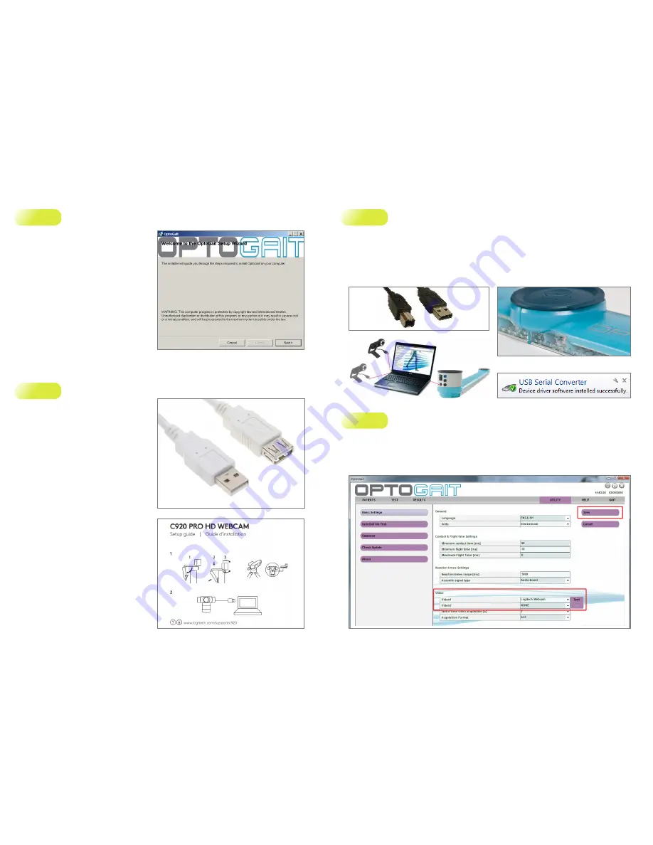
Install OptoGait.exe
a.
Launch the executable file “OptoGait.Exe“ found on
the Usb Key provided with the Kit, or downloaded
from
www.optogait.com
website;
b.
Follow the wizard (Fig. 1) by clicking “
Next>
”
until the software is completely installed;
c.
DO NOT RUN
the software, until you perform
the steps 2 and 3.
Step 1
Figure 3
Attach the webcam and install driver updates
a.
Attach the Logitech webcam to the PC’s USB port and
wait until the driver is completely installed. For longer
distance than 1,5 mt. please use the white USB
extension cable (Fig. 2);
b.
If you’re using your webcam with Windows®
10/8.1/8, the software required is downloaded
automatically when you connect your webcam
for the first time, and installed silently in the
background.
Important: Make sure you’re connected to the Internet,
so the software can be downloaded.
If you’re using your webcam with Windows® 7 or
Windows Vista®, you must install the Logitech®
Webcam Software, available from:
logitech.com/downloads
Step 2
Attach the OptoGait Hardware
a.
Connect the black USB cable (Fig. 4) from the OptoGait RX Bar to the PC;
b.
Power on the system by toggling the switches on each bar. You should see near the power socket a green-flashing
LED indicating batteries are charged. In case the LED is red-flashing, connect the power (see par. 4.3 on user
manual);
c.
Align the TX and RX bars in front of each other (max 6 meters distance) until the LED status indicator positioned along the
RX bar (Fig. 5) become from “red” to “green“;
d.
Wait until the driver is successfully installed (Fig. 7) before moving to the next Step 4.
Step 3
Figure 8
Launch the OptoGait Software and select the webcam
a.
Launch the software by double-clicking the OptoGait desktop icon;
b.
Choose the desired language and wait until the software is completely loaded;
c.
To select and test the webcam, click “Utility” on the Main Menu and then the “Basic Settings” button in the left column.
d.
In the Video Section, choose the
Logitech Webcam [model]
from the dropdown menu and then click the “Test”
button (Fig.8);
Step 4
Figure 6
Figure 7
Figure 5
Figure 4
Figure 1
Figure 2


