background image


BIGHORN_March 2020.docx


March 26, 2020 

Page 

9 of 36


5. 

  BIGHORN – VFD BASICS 

  The VFD (Variable Frequency Drive) controls the speed of the electrical motor (and subsequently the pump 

head) by changing the Frequency (Hertz).  

  The VFD is shipped with a minimum factory setting of 30 Hz.  This will produce the minimum speed at which 

the pump is still capable of adequate oil distribution within the crankcase.  This minimum setting will ensure 

reduced motor and pump wear. 

  The VFD is factory set at a maximum of 60 Hz.  This will produce the maximum designed water flow of the 

pump at 1000 psi / 70 Bar. 

  For more details on the VFD drive, the readings and fault status refer to the WEG Drive supplement which 

is enclosed. 

6. 

MICROCOOL BIGHORN  - STARTING THE SYSTEM 

6.1 

SYSTEM FLUSH 

The system must be flushed before pressurization. This removes any contaminants such as dirt, brass filings or 

Teflon tape that have found their way into the system. At the end of each atomization line, there is a plug or an 

automatic drain valve. 

Do not

 install plugs or automatic drain valves until the system has been completely flushed. 

6.2 

WATER & DRAIN VALVES 

Turn on the water supply to the pump module. Ensure that the drain valves or plugs at the end of lines are not 

installed. 
6.3 

TURN ON POWER 


1. 

Turn on the power supply to the BIGHORN module, and then 

turn the circuit breaker  switch  mounted  inside the electrical 

enclosure to the on position. Ensure the VFD reads “RDY”. 

2. 

To start the pump, switch the “MAN/OFF/AUTO” switch to the 

MAN position. 
6.4 

PUMP IS RUNNING 

The pump system is now in operation. The VFD will increase the 

speed of the motor / pump to maximum speed (60 Hz) to fill the 

manifold and nozzle lines. 


Switch to Manual ‘MAN’ Position 

Summary of Contents for BIGHORN 1000

Page 1: ...1 of 36 Fog System 2020 Installation Maintenance Manual Version 3 26 BIGHORN Series MicroCool Web site www microcool com Email info microcool com 72216 Northshore St 103 104 Thousand Palms CA 92276 U...

Page 2: ...2 4 ULTRAVIOLET WATER PURIFIERS OPTIONAL 6 2 5 REVERSE OSMOSIS WATER TREATMENT OPTIONAL 6 3 INSTALLATION OF THE PUMP MODULE 7 3 1 PRE INSTALLATION PROCEDURE 7 3 2 POSITIONING THE PUMP MODULE 7 3 3 WAT...

Page 3: ...12 10 1 CRANKCASE OIL 12 10 2 TYPE OF CRANKCASE OIL 12 10 3 ELECTRICAL MOTOR MAINTENANCE 12 10 4 INLET WATER FILTER 12 10 5 ATOMIZATION HOSE AND MANIFOLD 13 10 6 SYSTEM FLUSH SHUT DOWN WINTERIZING 13...

Page 4: ...5 4 SPECIAL CONSIDERATIONS 20 16 HOSE CLAMP INSTALLATION TECHNIQUE 21 16 1 SPECIAL CONSIDERATIONS 21 16 2 FLEXIBLE MANIFOLD OR FLEXIBLE NOZZLE LINE RELIEF ROUTING 22 17 ORIENTATION OF ATOMIZATION NOZZ...

Page 5: ...crankcase oil must be changed after the first 50 hours of operation and from then on once every 500 hours or every 6 months whichever comes first synthetic 75w 90 gear oil is recommended for all appli...

Page 6: ...r is suitable for atomization Well water river water and the like should be tested before atomizing If an analysis indicates any unusually high levels of undesirable elements proper treatments are ava...

Page 7: ...1 40 Correct water pressure and supply rate are essential to pump operation All pump modules require a minimum of 20 P S I 1 40 BAR and a maximum of 90 P S I 6 20 BAR while in operation The pressure...

Page 8: ...Please refer to the serial number data plate on the pump module for more details 4 3 ELECTRICAL POWER SUPPLY The power supply to the pump module must be hard wired to a correctly rated fuse protected...

Page 9: ...FLUSH The system must be flushed before pressurization This removes any contaminants such as dirt brass filings or Teflon tape that have found their way into the system At the end of each atomization...

Page 10: ...at 20 PSI 1 4 Bar and does not require any further adjustment 6 6 SYSTEM RUN Let the module run for five minutes making sure that there is a good flow of water running out the end of each atomization...

Page 11: ...its preprogrammed drain sequence 8 2 RAMP DOWN The pump will electronically ramp down slow to a stop to avoid any water hammer After a 3 second delay the inlet solenoid valve will close and the drain...

Page 12: ...hould be changed after every 500 hours of operation Examples of 500 hours operation 15 weeks of 5 hour operation per day 9 weeks of 8 hour operation per day 6 weeks of 12 hour operation per day 3 week...

Page 13: ...11 4 NOZZLE DIRECTION Avoid pointing atomization nozzles directly at or towards any close object or surface where the fog can collide before evaporation Adjust ROC nozzles or Flex line nozzles to avo...

Page 14: ...ard brass fittings Teflon tape must always be used on the male threads of any fitting to create a liquid tight seal However the stem component of a reusable hose fitting i e that bit that screws down...

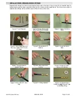
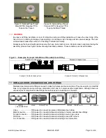
Page 15: ...hod used to fit them to hose is the same Figure 1 Tools Required Figure 2 Screw Ferrule onto Hose Counter Anti Clockwise Figure 3 Tighten Ferrule on Hose Figure 4 Stop Tightening when the Line is with...

Page 16: ...sion fittings are used to make high pressure line connections They are used to join manifold lines to high pressure pump modules atomization lines and for numerous other applications Although there ar...

Page 17: ...h the advanced back ferrule geometry Insert tubing into the compression tube fitting Fig 1 Make sure that the tubing rests firmly on the shoulder of the tube fitting body and that the nut is finger ti...

Page 18: ...atomization line to structures of greenhouses storage houses waste load out facilities perimeter fencing around sludge ponds or strung between poles to span across sewage lagoons The possibilities ar...

Page 19: ...round below the Aircraft Cable Do not allow the atomization line to become excessively dirty and make sure the protective caps on the end of the nozzles and lines remain in place While on the ground i...

Page 20: ...ort lengths of Aircraft Cable have been attached to a roof structure and then dropped and fixed to the Aircraft Cable supporting the atomization line at an interval of 10 to 15 feet 3 to 4 5 MT Please...

Page 21: ...o position and attach the clamp to the support surface using a screw When attaching to masonry it will be necessary to drill a hole and use a wall anchor and screw to hold the hose clamp in position I...

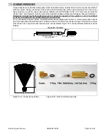
Page 22: ...fitting leakage or damage not covered under warranty 17 ORIENTATION OF ATOMIZATION NOZZLES The atomization nozzles mounted in flexible and ROC atomization lines are 360 adjustable After the atomizati...

Page 23: ...ring the installation The nozzles may have come loose during transportation and installation Most applications require nozzles to be finger tight only Mechanical tools to tighten nozzles should only b...

Page 24: ...me dislodged Wear eye protection Remember a blocked or badly performing nozzle reduces the capacity of the system to cool or humidify It is similar to shutting off air conditioning units one at a time...

Page 25: ..._March 2020 docx March 26 2020 Page 25 of 36 Stiff Wire Brush Cleaning Stiff Wire Wheel in Portable Devise MicroCool Nozzle Cleaning Tool MicroCool Part VTB0001 MicroCool Part VTB0002 MicroCool Part T...

Page 26: ...ions Page 1 of 1 Issued to MICROCOOL 72216 Northshore St Unit 103 104 THOUSAND PALMS CA 92276 This is to certify that representative samples o INDUSTRIAL CONTROL PANELS USL CNL Industrial control pane...

Page 27: ...me provided above shall constitute fulfillment of all liabilities of the seller to the purchaser with respect to or arising out of the goods whether based on contract negligence strict tort or otherwi...

Page 28: ...BIGHORN_March 2020 docx March 26 2020 Page 28 of 36 22 BIGHORN ILLUSTRATIONS...

Page 29: ...BIGHORN_March 2020 docx March 26 2020 Page 29 of 36 22 1 BIGHORN FRONT EXTERNAL VIEW...

Page 30: ...BIGHORN_March 2020 docx March 26 2020 Page 30 of 36 22 2 BIGHORN BACK EXTERNAL VIEW...

Page 31: ...BIGHORN_March 2020 docx March 26 2020 Page 31 of 36 22 3 BIGHORN RIGHT EXTERNAL VIEW...

Page 32: ...BIGHORN_March 2020 docx March 26 2020 Page 32 of 36 22 4 BIGHORN LEFT EXTERNAL VIEW...

Page 33: ...BIGHORN_March 2020 docx March 26 2020 Page 33 of 36 22 5 BIGHORN TOP EXTERNAL VIEW...

Page 34: ...BIGHORN_March 2020 docx March 26 2020 Page 34 of 36 22 6 BIGHORN TOP INTERNAL VIEW...

Page 35: ...BIGHORN_March 2020 docx March 26 2020 Page 35 of 36 22 7 BIGHORN CONTROL PANEL VIEW...

Page 36: ...BIGHORN_March 2020 docx March 26 2020 Page 36 of 36 22 8 NOTES...

Reviews: