

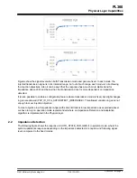


Figures show the signal level when both Transmission mode and gain are fixed. In each mode, the
injected transmission signal is in its intended range, but out of such range, each mode is not achieving
the injection objectives. Also it can be seen that the response has a much more stable trend for
impedance above 20Ω, and below that, the transmission driver is more dependent on impedance
detected.
It is also possible to enable a configuration feature where transmission mode is fixed, but slight changes
in gain are allowed (PHY_ID_CFG_AUTODETECT_IMPEDANCE). This allowed variation in gain is not
enough to meet injection objective.
To meet objective in all impedance range (with some limitations in low impedance as explained above),
we have to rely on operation mode recommended where an Impedance Detection and Adaptation
algorithm is implemented in the Physical layer.
2.2
Impedance Detection
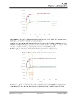
The following figure shows the response in AUTO_STATE_VAR_GAIN (1) operation mode, where the
system updates its response depending on the impedance detected in reception and following signal
level, compared to the fixed modes:
PL360
Physical Layer Capabilities
©
2018 Microchip Technology Inc.
User Guide
DS50002818A-page 5