background image

Inhalt

Einleitung........................................................................................................................................................1

Funktionen und Merkmale.......................................................................................................................1

1.  Normen und Sicherheitsrichtlinien.......................................................................................................... 3

1.1.  Definition der Teilenummer...........................................................................................................3
1.2.  Elektrische Kompatibilitäts-Zulassungen......................................................................................3
1.3.  Sicherheitsstandard-Zulassungen................................................................................................3
1.4.  CE-Kennzeichnung...................................................................................................................... 3
1.5.  GS-Übereinstimmung...................................................................................................................3
1.6.  Überspannungs-/Blitzschutz.........................................................................................................3
1.7.  Sicherheitshinweise......................................................................................................................4

2.  Information en Matière de Sécurité......................................................................................................... 5

2.1.  Directives Générales.................................................................................................................... 5
2.2.  Mises en Garde............................................................................................................................ 5

3.  Installation des PoE Midspan-Geräts......................................................................................................6

3.1.  Teileliste........................................................................................................................................6
3.2.  Zusätzliche Teile...........................................................................................................................6
3.3.  Installation des Midspan-Geräts...................................................................................................7

4.  Installation der Kabel.............................................................................................................................11

4.1.  DC-Netzkabelinstallation............................................................................................................ 11
4.2.  RJ45-Netzkabelinstallation.........................................................................................................12
4.3.  Daten- und Stromanschluss....................................................................................................... 13

5.  Fehlersuche.......................................................................................................................................... 14

5.1.  Vorläufige Schritte...................................................................................................................... 14
5.2.  Schritte zur Fehlersuche............................................................................................................ 14

6.  Technische Daten..................................................................................................................................15

6.1.  Umgebungsdaten....................................................................................................................... 15
6.2.  Elektrische Daten....................................................................................................................... 15
6.3.  Schnittstelle................................................................................................................................ 15

7.  Technischer Support............................................................................................................................. 16

8.  Überarbeitungsübersicht....................................................................................................................... 17

Informationen zu Microchip.......................................................................................................................... 18

The Microchip Website..........................................................................................................................18
Product Change Notification Service.................................................................................................... 18
Customer Support................................................................................................................................. 18
Microchip Devices Code Protection Feature.........................................................................................18
Legal Notice.......................................................................................................................................... 18
Trademarks........................................................................................................................................... 19
Quality Management System................................................................................................................ 20
Worldwide Sales and Service................................................................................................................21

 PD-9501-10GCO/DC

©

 2022 Microchip Technology Inc.

and its subsidiaries

 User Guide

DS50003347A-page 2

Summary of Contents for PD-9501-10GCO/DC

Page 1: ...The PD 9501 10GCO DC unit supports emerging wireless 10 Gbps devices such as wireless IEEE 802 11ac access points PoE Midspans power devices that are PoE enabled or equipped to receive PoE These devices are called power devices PDs Features PD 9501 10GCO DC midspan unit offers the following key features Outdoor Rated IP66 and IP67 Extended Temperature Range 40 C to 65 C Supports 10 100 1000 Mbps a...

Page 2: ...3 3 Midspan Unit Installation 8 4 Installation of Cables 11 4 1 DC Power Cable Installation 11 4 2 RJ45 Cable Installation 12 4 3 Data and Power Connection 13 5 Troubleshooting 14 5 1 Preliminary Steps 14 5 2 Troubleshooting Steps 14 6 Specifications 15 6 1 Environmental Specifications 15 6 2 Electrical Specifications 15 6 3 Interface 15 7 Technical Support 16 8 Revision History 17 The Microchip W...

Page 3: ...Quality Management System 20 Worldwide Sales and Service 21 PD 9501 10GCO DC 2022 Microchip Technology Inc and its subsidiaries User Guide DS50003347A page 3 ...

Page 4: ...icrochip for a complete list of safety certifications UL IEC EN62368 1 UL IEC EN60950 22 GS Compliance 1 4 CE Marking CE marking on this product indicates that this product complies with the Electromagnetic Compatibility EMC Directive 1 5 GS Compliance GS marking on this product indicates that this product complies with the German Product Safety Act 1 6 Surge Lightening Protection Microchip s PD 9...

Page 5: ...ent and can pose a fire hazard If voltage indicated on the label is different from the power outlet voltage do not connect midspan to this outlet All wiring and connections must comply with NFPA 70 NEC and state and local regulatory requirements Power supply cord must not be attached to the building surface or run through walls ceilings floors and similar openings in the building structure Measure...

Page 6: ...mager l équipement et constituer un risque d incendie Si le voltage indiqué sur l étiquette est différent du voltage de la source d alimentation ne pas connecter le midspan à cette prise Tous les câblages et connexions doivent être conformes à la norme NFPA 70 NEC et aux exigences réglementaires locales et nationales Le cordon d alimentation ne doit pas être fixé à la surface du bâtiment ni passer...

Page 7: ...lowed range 3 Earth ground screw must be connected to earth ground in all types of installations 3 1 Parts List The following table lists the parts included in the kit Quantity Component 1 60W midspan outdoor model 1 DC female connector 1 Quick installation guide 3 2 Additional Parts The following table lists the additional parts recommended for midspan installation Quantity Part 1 Screwdriver 1 W...

Page 8: ...ot cover the midspan or block the airflow to the PoE with any foreign objects Keep the midspan away from excessive heat and free from vibration Ensure that the cable length from the Ethernet network source to the terminal does not exceed 100 meters 333 feet The midspan is not a repeater and does not amplify the Ethernet data signal The midspan has no ON OFF switch simply plug the midspan into an D...

Page 9: ...ing Follow the procedure to mount the unit directly to a wall 1 Using the screw holes of the midspan as a template put marks on the mounting surface a wall of wood brick or concrete to mark drill points and drill four holes 2 With the unit attached to the mounting surface insert four mounting screws through the screw holes on the unit and into the mounting surface Notes For bricks or concrete wall...

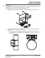
Page 10: ... head screws and tighten the pan head screws to 1 1 Nm 2 Place the midspan pole bracket assembly onto the pole Tighten the midspan pole bracket assembly to the pole using worm clams as shown in the following figures Notes Pole bracket supports poles with diameters ranging from 60 mm to 200 mm 2 5 inches to 8 inches The unit must be installed with DATA IN and DATA PWR OUT ports facing down as shown...

Page 11: ...N F or H07RN F Voltage rating 300V or better recommended Temperature range 40 to 65 or better recommended Cable size 16 AWG 2C 1 5 mm2 2C Cable outer dimension Dia 3 16 in to 3 8 in Dia 5 0 mm 9 5 mm Approved for indoor and outdoor applications The following figure shows the DC cable connection to the midspan unit Figure 4 1 DC Cable Connection 1 5 Nm 8mm 5 16 in 25mm 1 in 0 5 Nm 2 1 i PD 9501 10G...

Page 12: ...d the upper cap towards the midspan and hand tighten the upper cap onto the DATA IN port Note Secure the gland until the rubber gasket is firmly closed around the cable 4 Repeat step 1 to step 3 to connect the RJ45 cable to the DATA PWR OUT port Notes 1 Use cable up to 5 Gig Cat 5e and above outdoor grade 2 Use cable up to 10 Gig Cat 6 and above outdoor grade PD 9501 10GCO DC Installation of Cable...

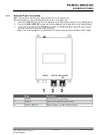
Page 13: ... in the following figure 3 Connect DC power lines from the LINE IN terminal item 1 in the following figure to main DC power Ensure that the power outlet is nearby and easily accessible Note Connect the midspan unit to a weather proof DC power source box that meets IP66 and IP67 ratings Label Description 1 LINE IN Power Input 12 VDC to 24 VDC 2 DATA IN Data In to the Ethernet network switch 3 DATA ...

Page 14: ...Remove and reapply power to the device during power up sequence PD does not operate 1 Verify that the port is enabled midspan did not detect a PD 2 Verify that the PD is designed for PoE operation 3 Verify that you are using a standard Category 5 5e 6 straight wired cable with four pairs according to data rate 4 If an external power splitter is in use replace it with a viable splitter 5 Verify tha...

Page 15: ... Input voltage 10 8 VDC 30 VDC Input current 8A maximum Available output power maximum 60W Nominal output voltage 54 VDC 6 3 Interface Table 6 3 Interface Parameter Type Input Data In Ethernet 10 100 1000Base T RJ45 female socket Output DATA PWR OUT Ethernet 10 100 1000 and 2 5Gig 5Gig 10Gig Base T plus 54 VDC RJ45 female socket with DC voltage on wire pairs 7 8 4 5 and 1 2 3 6 DC Power In 2 Pins ...

Page 16: ...consult the Microchip technical support team through the website or contact on the following number USA Canada Telephone 1 877 480 2323 Internet www microchip com support PD 9501 10GCO DC Technical Support 2022 Microchip Technology Inc and its subsidiaries User Guide DS50003347A page 16 ...

Page 17: ...8 Revision History Revision Date Description A 09 2022 Initial Revision PD 9501 10GCO DC Revision History 2022 Microchip Technology Inc and its subsidiaries User Guide DS50003347A page 17 ...

Page 18: ...ting of sales offices and locations is included in this document Technical support is available through the website at www microchip com support Microchip Devices Code Protection Feature Note the following details of the code protection feature on Microchip devices Microchip products meet the specifications contained in their particular Microchip Data Sheet Microchip believes that its family of pr...

Page 19: ...gner QTouch SAM BA SenGenuity SpyNIC SST SST Logo SuperFlash Symmetricom SyncServer Tachyon TimeSource tinyAVR UNI O Vectron and XMEGA are registered trademarks of Microchip Technology Incorporated in the U S A and other countries AgileSwitch APT ClockWorks The Embedded Control Solutions Company EtherSynch FlashTec Hyper Speed Control HyperLight Load IntelliMOS Libero motorBench mTouch Powermite 3...

Page 20: ...ement System For information regarding Microchip s Quality Management Systems please visit www microchip com quality PD 9501 10GCO DC 2022 Microchip Technology Inc and its subsidiaries User Guide DS50003347A page 20 ...

Page 21: ...amen Tel 86 592 2388138 China Zhuhai Tel 86 756 3210040 India Bangalore Tel 91 80 3090 4444 India New Delhi Tel 91 11 4160 8631 India Pune Tel 91 20 4121 0141 Japan Osaka Tel 81 6 6152 7160 Japan Tokyo Tel 81 3 6880 3770 Korea Daegu Tel 82 53 744 4301 Korea Seoul Tel 82 2 554 7200 Malaysia Kuala Lumpur Tel 60 3 7651 7906 Malaysia Penang Tel 60 4 227 8870 Philippines Manila Tel 63 2 634 9065 Singap...

Page 22: ...en sicheren und zuverlässigen Betrieb in Außenumgebungen für Standard PoE Datenendgeräte gewährleistet Der PD 9501 10GCO DC unterstützt neue drahtlose 10 Gbit s Geräte wie z B drahtlose IEEE 802 11ac Access Points Der PoE Midspan versorgt Geräte die PoE fähig oder für den Empfang von PoE ausgerüstet sind Diese Geräte werden als Powered Devices PDs bezeichnet Funktionen und Merkmale Das Midspan Ger...

Page 23: ...n Geräts 7 4 Installation der Kabel 11 4 1 DC Netzkabelinstallation 11 4 2 RJ45 Netzkabelinstallation 12 4 3 Daten und Stromanschluss 13 5 Fehlersuche 14 5 1 Vorläufige Schritte 14 5 2 Schritte zur Fehlersuche 14 6 Technische Daten 15 6 1 Umgebungsdaten 15 6 2 Elektrische Daten 15 6 3 Schnittstelle 15 7 Technischer Support 16 8 Überarbeitungsübersicht 17 Informationen zu Microchip 18 The Microchip...

Page 24: ...ine vollständige Liste der Sicherheitszertifizierungen zu erhalten UL IEC EN62368 1 UL IEC EN60950 22 GS Übereinstimmung 1 4 CE Kennzeichnung Die CE Kennzeichnung auf diesem Produkt zeigt an dass dieses Produkt die Richtlinie zur elektromagnetischen Verträglichkeit EMV erfüllt 1 5 GS Übereinstimmung Das GS Zeichen auf diesem Produkt bedeutet dass das Produkt dem deutschen Produktsicherheitsgesetz ...

Page 25: ...ie auf dem Etikett angegebene Spannung nicht mit der Spannung der Steckdose übereinstimmt darf der Midspan nicht an diese Steckdose angeschlossen werden Die gesamte Verkabelung und die Anschlüsse müssen den Anforderungen von NFPA 70 NEC sowie den staatlichen und örtlichen Vorschriften entsprechen Das Netzkabel darf nicht an der Oberfläche des Gebäudes befestigt werden oder durch Wände Decken Böden...

Page 26: ...dommager l équipement et constituer un risque d incendie Si le voltage indiqué sur l étiquette est différent du voltage de la source d alimentation ne pas connecter le midspan à cette prise Tous les câblages et connexions doivent être conformes à la norme NFPA 70 NEC et aux exigences réglementaires locales et nationales Le cordon d alimentation ne doit pas être fixé à la surface du bâtiment ni pas...

Page 27: ...lässigen Bereichs liegt 3 Die Erdungsschraube muss bei allen Installationsarten mit der Erdung verbunden werden 3 1 Teileliste In der folgenden Tabelle sind die im Kit enthaltenen Teile aufgeführt Menge Bauteil 1 60 W Midspan Modell für den Außenbereich 1 DC Buchse 1 Kurzanleitung zur Montage 3 2 Zusätzliche Teile In der folgenden Tabelle finden Sie die für die Montage des Midspan empfohlenen zusä...

Page 28: ...n Sie den Midspan nicht ab und blockieren Sie den Luftstrom zum PoE nicht mit Fremdkörpern Halten Sie den Midspan fern von übermäßiger Hitze und frei von Vibrationen Stellen Sie sicher dass die Kabellänge von der Ethernetnetzwerkquelle bis zum Endgerät 100 Meter 330 Fuß nicht überschreitet Dieser Midspan ist kein Repeater und verstärkt das Ethernetdatensignal nicht Der Midspan hat keinen EIN AUS S...

Page 29: ...ekt an einer Wand zu befestigen 1 Verwenden Sie die Schraubenlöcher des Midspan als Schablone markieren Sie die Bohrpunkte auf der Montageoberfläche eine Wand aus Holz Ziegel oder Beton und bohren Sie vier Löcher 2 Wenn das Gerät an der Montageoberfläche befestigt ist führen Sie vier Montageschrauben durch die Schrauböffnungen am Gerät und in die Montageoberfläche ein Anmerkungen Verwenden Sie für...

Page 30: ...chkopfschrauben auf 1 1 Nm an 2 Setzen Sie die Midspan Masthalterungsbaugruppe auf den Mast Ziehen Sie die Midspan Masthalterungsbaugruppe mit Schneckenschrauben am Mast fest wie in den folgenden Abbildungen gezeigt Anmerkungen Die Masthalterung unterstützt Masten mit einem Durchmesser von 60 mm bis 200 mm 2 5 Zoll bis 8 Zoll Das Gerät muss so installiert werden dass die Dateneingangs und Datenaus...

Page 31: ...PD 9501 10GCO DC Installation des PoE Midspan Geräts 2022 Microchip Technology Inc and its subsidiaries User Guide DS50003347A page 10 ...

Page 32: ...5RN F oder H07RN F Nennspannung 300 V oder besser wird empfohlen Temperaturbereich 40 bis 65 oder besser wird empfohlen Kabelgröße 16 AWG 2C 1 5 mm2 2C Kabelaußenmaße Durchm 3 16 Zoll 3 8 Zoll Durchm 5 0 mm 9 5 mm Zugelassen für Anwendungen im Innen und Außenbereich Die folgende Abbildung zeigt den Anschluss des DC Netzkabels an das Midspan Gerät Abbildung 4 1 DC Netzkabelanschluss 1 5 Nm 8mm 5 16...

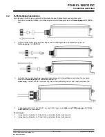
Page 33: ...appe in Richtung Midspan und ziehen Sie die obere Kappe am Dateneingangs Port DATA IN handfest an Anmerkung Sichern Sie die Verschraubung bis die Gummidichtung fest um das Kabel geschlossen ist 4 Wiederholen Sie Schritt 1 bis Schritt 3 um das RJ45 Kabel an den Daten und PWR Ausgangs Port Data und PWR OUT anzuschließen Anmerkungen 1 Verwenden Sie Kabel bis zu 5 Gig Cat 5e und darüber für den Außenb...

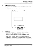
Page 34: ...thernet Netzwerk Element 3 in der folgenden Abbildung 3 Verbinden Sie die DC Stromleitungen vom LINE IN Anschluss Element 1 in der folgenden Abbildung mit dem DC Netzstrom Stellen Sie sicher dass die Steckdose in der Nähe und leicht zugänglich ist Anmerkung Schließen Sie das Midspan Gerät an eine wetterfeste DC Stromquelle an die den Schutzklassen IP66 und IP67 entspricht Etikett Beschreibung 1 LI...

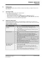
Page 35: ...nden Sie es erneut während des Einschaltvorgangs PD funktioniert nicht 1 Stellen Sie sicher dass der Port aktiviert ist der Midspan hat keinen PD erkannt 2 Stellen Sie sicher dass der PD für den PoE Betrieb ausgelegt ist 3 Stellen Sie sicher dass Sie ein gerade verdrahtetes Standardkabel der Kategorie 5 5e 6 mit vier Paaren je nach Datenrate verwenden 4 Falls ein externer Stromsplitter verwendet w...

Page 36: ...annung 10 8 VDC 30 VDC Eingangsstrom 8 A maximal Verfügbare Ausgangsleistung maximal 60 W Nennausgangsspannung 54 VDC 6 3 Schnittstelle Tabelle 6 3 Schnittstelle Parameter Typ Eingang Data In Ethernet 10 100 1000Base T RJ45 Buchse Ausgang DATA PWR OUT Ethernet 10 100 1000 und 2 5Gig 5Gig 10Gig Base T plus 54 VDC RJ45 Buchse mit DC Spannung auf Adernpaaren 7 8 4 5 und 1 2 3 6 DC Stromeingang DC Pow...

Page 37: ...eten wenden Sie sich an den technischen Support von Microchip über die Webseite oder unter der folgenden Nummer USA Kanada Telefon 1 877 480 2323 Internet www microchip com support PD 9501 10GCO DC Technischer Support 2022 Microchip Technology Inc and its subsidiaries User Guide DS50003347A page 16 ...

Page 38: ...rarbeitungsübersicht Überarbeitung Datum Beschreibung A 09 2022 Erste Überarbeitung PD 9501 10GCO DC Überarbeitungsübersicht 2022 Microchip Technology Inc and its subsidiaries User Guide DS50003347A page 17 ...

Page 39: ...stributor representative or ESE for support Local sales offices are also available to help customers A listing of sales offices and locations is included in this document Technical support is available through the website at www microchip com support Microchip Devices Code Protection Feature Note the following details of the code protection feature on Microchip products Microchip products meet the...

Page 40: ...ce tinyAVR UNI O Vectron and XMEGA are registered trademarks of Microchip Technology Incorporated in the U S A and other countries AgileSwitch APT ClockWorks The Embedded Control Solutions Company EtherSynch Flashtec Hyper Speed Control HyperLight Load IntelliMOS Libero motorBench mTouch Powermite 3 Precision Edge ProASIC ProASIC Plus ProASIC Plus logo Quiet Wire SmartFusion SyncWorld Temux TimeCe...

Page 41: ...ement System For information regarding Microchip s Quality Management Systems please visit www microchip com quality PD 9501 10GCO DC 2022 Microchip Technology Inc and its subsidiaries User Guide DS50003347A page 20 ...

Page 42: ...amen Tel 86 592 2388138 China Zhuhai Tel 86 756 3210040 India Bangalore Tel 91 80 3090 4444 India New Delhi Tel 91 11 4160 8631 India Pune Tel 91 20 4121 0141 Japan Osaka Tel 81 6 6152 7160 Japan Tokyo Tel 81 3 6880 3770 Korea Daegu Tel 82 53 744 4301 Korea Seoul Tel 82 2 554 7200 Malaysia Kuala Lumpur Tel 60 3 7651 7906 Malaysia Penang Tel 60 4 227 8870 Philippines Manila Tel 63 2 634 9065 Singap...

Reviews: