MRF24WN0MA/MB
DS50002410A-page 10
Advance Information
2015 Microchip Technology Inc.
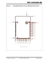
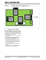
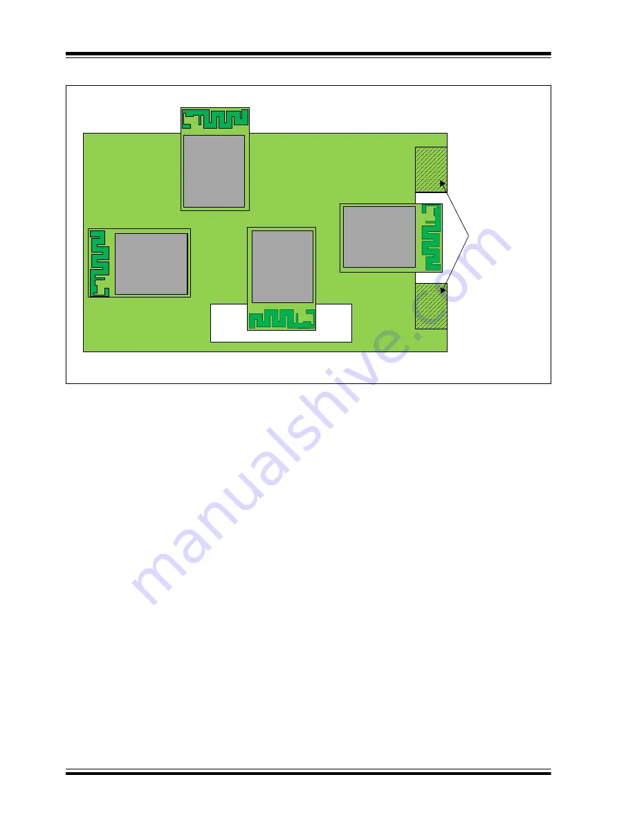
FIGURE 1-7:
MRF24WN0MA/MB HOST PCB EXAMPLE LAYOUT
1.3
Soldering Recommendations
The MRF24WN0MA/MB wireless module was assem-
bled using the IPC/JEDEC J-STD-020 Standard lead-
free reflow profile. The MRF24WN0MA/MB module
can be soldered to the host PCB using standard leaded
and lead-free solder reflow profiles.
To avoid damaging the module, adhere to the following
recommendations:
• Solder reflow recommendations are provided in
the Microchip Application Note,
AN233 "Solder
Reflow Recommendation"
(DS00233)
• Do not exceed a peak temperature (T
P
) of 250°C
• Refer to the solder paste data sheet for specific
reflow profile recommendations from the vendor
• Use no-clean flux solder paste
• Do not wash as moisture can be trapped under
the shield
• Use only one flow. If the PCB requires multiple
flows, apply the module on the final flow.
Best
Okay
Okay
Okay
No Copper
in these Areas
Summary of Contents for MRF24WN0MA
Page 14: ...MRF24WN0MA MB DS50002410A page 14 Advance Information 2015 Microchip Technology Inc NOTES...
Page 30: ...MRF24WN0MA MB DS50002410A page 30 Advance Information 2015 Microchip Technology Inc NOTES...
Page 32: ...MRF24WN0MA MB DS50002410A page 32 2015 Microchip Technology Inc NOTES...
Page 34: ...MRF24WN0MA MB DS50002410A page 34 Advance Information 2015 Microchip Technology Inc NOTES...


