


2017 Microchip Technology Inc.
DS50002556A-page 17
2.4
CONNECTING THE BOARD
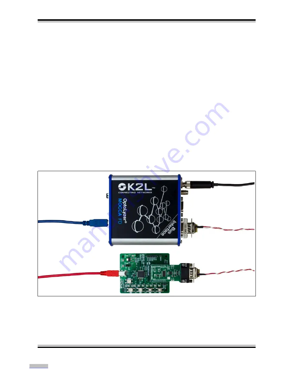
Figure 2-2
illustrates an example CAN FD network. The MCP2517FD click Board is
plugged into the MCP251XFD CAN FD Motherboard. A CAN FD tool from K2L is
connected to the MCP2517FD click Board using twisted pair wires.
The demonstration board is powered using a Mini-USB cable. Alternatively, the board
can be powered using a 5V power supply connected between 5VIN and GND1.
There are two terminations on the CAN bus:
• Two 60 Ohm resistors in series on the MCP2517FD click Board.
• A 120 Ohm termination resistor at the connector of the K2L OptoLyzer
®
MOCCA
FD tool.
2.5
OPERATION
The user can write firmware for the MCU in order to create a custom CAN FD node.
Check the MCP2517FD product page for the firmware API and for code examples.
The RST button can be used to reset the MCU. Switches S1-S4 can be used to trigger
the transmission of CAN FD messages to the CAN FD tool. LEDs D1-D8 can be
controlled by the CAN FD tool using CAN FD messages.
All I/O pins of the MCP2517FD are easily accessible through pin headers.
The differential CAN bus signals, CAN_H and CAN_L, are accessible on the
MCP2517FD click Board, or on the DB9 connector: CAN_H on pin 7, and CAN_L on
pin 2.
FIGURE 2-2:
Connecting the MCP251XFD CAN FD Motherboard.
Downloaded from
Downloaded from
Downloaded from
Downloaded from
Downloaded from
Downloaded from
Downloaded from
Downloaded from
Downloaded from
Downloaded from
Downloaded from
Downloaded from
Downloaded from
Downloaded from
Downloaded from
Downloaded from
Downloaded from


