


MCP1643 Synchronous Boost LED Constant Current Regulator Evaluation Board User’s Guide
DS20005196A-page 14
2013 Microchip Technology Inc.
2.2
GETTING STARTED
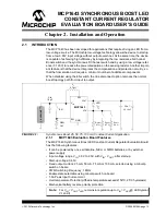
The MCP1643 Synchronous Boost LED Constant Current Regulator Evaluation Board
is fully assembled and tested to evaluate and demonstrate the MCP1643 product. This
board requires the use of an external power supply or an AA battery.
2.2.1
Power Input and Output Connection
2.2.1.1
POWERING THE MCP1643 SYNCHRONOUS BOOST LED CONSTANT
CURRENT REGULATOR EVALUATION BOARD
Soldered test points are available for input voltage connections. The maximum input
voltage should not exceed 2.5V. The output current will not remain in regulation for
input voltages that are greater than, or equal to, the forward voltage of the LED. White
LEDs have V
F
typical between 2.5 and 3.5V, depending on the LED drive current.
The MCP1643 Synchronous Boost LED Constant Current Regulator Evaluation Board
was designed to be used in the process of validating the device. The package selected
for the MCP1643 Synchronous Boost LED Constant Current Regulator Evaluation
Board is the MSOP-8.
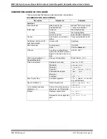
SW1 is the Enable switch, which gives the state of the converter, ON or OFF. A sol-
dered test point that can be used for PWM dimming is also available for the EN pin. The
second switch is used to modify the value of the sense resistor, in order to modify the
LED current and achieve analog dimming (for the position of the switches and output
current, see Table 2-1).
2.2.1.2
BOARD POWER UP PROCEDURE
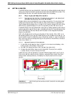
1. Connect the input supply as shown in Figure 2-2 or connect an AA battery in the
battery holder on the bottom of the board.
2. Use SW1 to change the state of the converter from ON to OFF.
3. Change the value of the output current using SW2. There are four available
currents: 25 mA, 50 mA,75 mA and 100 mA.
Additional test points are available to visualize different signals (SW, output current,
FB) or to modify the output current by dimming, using the EN pin. Note: Due to the
holder reverse polarity protection, the battery can only be inserted in the correct
position.
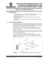
FIGURE 2-2:
MCP1643 Synchronous Boost LED Constant Current Regulator
Evaluation Board Setup.
+
_
Power Supply


