


Introduction
2017 Microchip Technology Inc.
DS70005311A-page 15
1.3
STARTER KIT FUNCTIONALITY AND FEATURES
1.3.1
Development Board
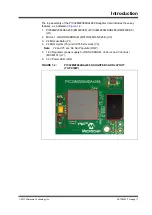
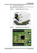
Representations of the layout of the development board included in the PIC32MZ DA
Family Starter Kit are shown in
through
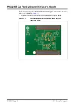
The top assembly of the PIC32MZ DA SK Base Board includes these key features, as
indicated in
.
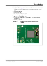
1.
USB Micro-B power supply connector (J4).
2.
Headers to connect PIC32MZ2064DAx288/PIC32MZ2064DAx169 CPU Daugh-
ter Cards (J2, J3).
3.
Micro-SD slot (J10).
4.
Headers for flexible Ethernet PHY options (J9).
5.
USB Type-A connector for PIC32 USB host based applications (J7).
6.
USB Micro-B connector for USB-to-UART communication (J5).
7.
Three push button switches for user-defined inputs (S1, S2, and S3).
8.
Three user-defined indicator LEDs (D3, D4, and D5).
9.
Jumper for using or disconnecting the on-board debugger (J17).
10. Connector for an external debugger, such as MPLAB® REAL ICE or MPLAB ICD
3 (J12).
11. 40-pin expansion connector for adding external boards (J15).
For details on these features, refer to
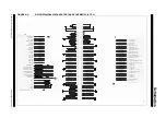
FIGURE 1-2:
PIC32MZ DA SK BASE BOARD LAYOUT (TOP VIEW)
Note:
When running self-powered USB device applications, open the jumper JP1
to prevent possibly back-feeding voltage onto the V
BUS
from one port on
the host to another (or from one host to another).
1
2
2
3
4
4
5
6
7
8
9
10
11


