


2
MAE2200
®
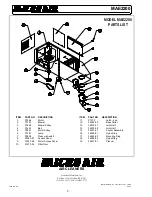
MODEL MAE2200 SPECIFICATIONS
Input Volts:
208-230/460 VAC 60Hz, 3-phase
Max. Current: 208-230 VAC - 7.2 amps
460 VAC - 3.6 amps
Motor:
2 HP 3-phase
TEFC Motor
Dimensions: 22"H. x 26"W. x 78"L. (cabinet and plenum)
Shipping WT: 375 lbs. without arms
Actual WT:
325 lbs. without arms
ARM SPECIFICATIONS
Arm Length (Horizontal Reach):
14' - 8" dia.
10' - 8" dia.
8' - 8" dia.
Actuator:1/8 HP totally enclosed motor, 12" stroke at 35 in/min.
Input Volts:
120 VAC 60 Hz
Current:
2.1 amps
Control Circuit:
24 VAC
Hood Lamp:
12 VAC halogen at 4 amps
Weights:
8" dia. - 14' = 48 lbs
8" dia. - 10' = 40 lbs
8" dia. - 8' = 35 lbs
PACKAGE CONTENT
1 ea.
MAE2200 with Plenum
1 ea.
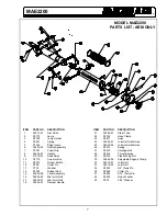
*Arm Assembly
1 ea.
Owners Manual
1 ea.
Arm Installation Kit
*Dual Arm units will contain two each of this item.
UNCARTONING INSTRUCTIONS
1.
The MAE2200 is packaged in two cartons. Carton one
has the MAE2200 with plenum and base collars banded
to the wooden skid. Carton two contains the arm
assembly(s).
2.
Cut the metal banding that secures the unit to the skid and
remove all cartoning, plastic wrap and padding.
3.
Remove blower access panel. Inspect blower, motor, belt
tension and power leads for damage. Replace blower
access panel after inspection is complete. Report any
shipping damage to freight line carrier.
4.
Open large door on the side of cabinet. Lift handles
outward and rotate to open door. Remove the plastic bag
from the filter and cut the paper band that is holding the
filter pockets in place. Reinstall the bag filter.
5.
Open carton two and remove arm. Remove packaging
supports from arm assembly. Be careful not to damage the
steel tubes on the arm during unpackaging.
6.
Inspect the arm for damage that may have been caused
during shipping. Immediately report any such damage to
the shipping carrier.
7.
Examine the arm and compare it to the parts list
description to verify that all components have been
received. If a component is missing from the assembly,
contact your Micro Air Representative.
INSTALLATION INSTRUCTIONS
CAUTION: THIS UNIT WITHOUT THE ARMS WEIGHS
APPROXIMATELY 325 POUNDS. THEREFORE,
APPROPRIATE MANPOWER OR EQUIPMENT IS
RECOMMENDED FOR SAFE INSTALLATION.
CAUTION: DO NOT ATTEMPT TO MOUNT UNIT USING
THE FOUR THREADED HOLES ON THE BOTTOM SIDE
OF CABINET.
1.
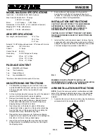
Install unit from solid structural support. Unit may then be
suspended with a rigid hanger assembly having sufficient
strength to support cabinet and the additional uneven load
of arm assembly(s) fully extended. (See
FIG. 1
.)
WARNING: DO NOT ATTEMPT TO INSTALL BY
SUSPENDING WITH CHAINS. ALL THREAD, ANGLE IRON,
OR OTHER FIXED SUPPORTS ARE REQUIRED.
ARM INSTALLATION INSTRUCTIONS
NOTE:
Due to the numerous system combinations available,
some of the following installation steps may not be applicable.
Follow steps that directly address the specific system being
installed.
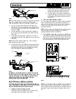
1.
Assemble the arm(s) to the base collar using the hardware
preassembled to the arm as shown in
FIG. 2
.
FIG. 1
FIG. 2