


Micrel, Inc.
SY88147DL Evaluation Board
January 2006
4
M9999-011606-A
or (408) 955-1690
Measurements
The SY88147DL evaluation board assumes the use of
a 50
Ω
scope to terminate the SY88147DL. The
following sub-sections detail various metrics that the
SY88147DL evaluation board can measure:
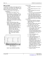
1. Eye pattern generation including jitter and
rise/fall times:
a. Set 70004’s Data amplitude to 5mV
PP
.
b. Press Autoscale on oscilloscope. The eye
pattern should automatically display on the
scope. If not, verify the steps listed in the
“Setup for Measurements” section are
completed. Sometimess the waveform
needs to be manually adjusted to fit the
display. Use the Time Scale and Voltage
Scale knobs on the front panel of the scope
to adjust this.
c. Observe measurements on scope’s
display. The rise and fall times should be
less than 260ps, amplitude around 800mV
(1600mV
pp
) and jitter around 10ps
RMS
.
i. Note that the output amplitude varies
with the input amplitude until the
SY88147DL enters limiting mode at
around 12.5mV
pp
input. The
SY88147DL has a typical gain of
42dB. Hence, 5mV
pp
input will give
only 630mV
pp
output, whereas
20mV
pp
input will give 1600mV
pp
output.
Figure 2. Typical SY88147DL Eye Pattern
2. Mask testing:
a. Press Eye/Mask Mode on front panel of
scope.
b. Choose Mask Testing from on-screen
display.
c. Choose Open Mask from on-screen
selection list.
i. Select and open the appropriate Mask
d. Choose Start Mask Testing from on-
screen selection list. Waveform should
automatically display with appropriate
mask regions and testing will start. If not,
verify the steps listed in the “Setup for
Measurements” section are completed.
3. BER testing:
a. Feedback the SY88147DL evaluation
board’s DOUT output to the 70843V’s
BERT Data input.
b. Feedback the 70843V’s Clock output to
the 70843V’s BERT Clock input.
c. Set 70004’s Data amplitude to 5mV
PP
.
d. From the 70004A’s Gating menu:
i. Choose a gate condition. The options
are: gate by time, errors or bits.
Choose bits, but this is of no
relevance because there should be
no errors, and the test will run forever
until manually interrupted if gate by
errors is chosen.
ii. Choose single gating period
iii. Choose run gating
iv. 70004A will reset error count and
synchronize SY88147DL’s
transmitted bit stream to 70843V’s
generated bit stream. If
synchronization does not occur, it is
sometimes due to cable length. Try
using different length cables (each
pair is of equal length, of course) is to
achieve synchronization. If this is
unavailable, another trick is to adjust
the 83752A’s frequency to a slightly
higher or lower value.
v. At the end of gating period, there
should be no errors.


