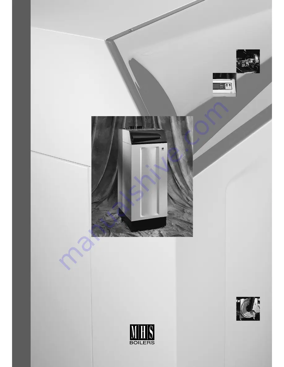
G A S F I R E D H I G H E F F I C I E N C Y /
C O N S D E N S I N G U L T R A L O W N O x B O I L E R
S I N G L E U N I T O U T P U T 1 2 0 k W
I N S T R U C T I O N S F O R I N S T A L L A T I O N ,
S E R V I C I N G & O P E R A T I O N
STRA
TA
2
Page 1: ...G H E F F I C I E N C Y C O N S D E N S I N G U L T R A L O W N O x B O I L E R S I N G L E U N I T O U T P U T 1 2 0 k W I N S T R U C T I O N S F O R I N S T A L L A T I O N S E R V I C I N G O P E...
Page 2: ...5 8 1 Connecting Third Fourth Fifth Sixth Seventh and Eighth Units page section 25 5 8 2 Boiler Manager RVA 47 Installation Procedure Normally Factory Fitted 26 5 8 3 Mixing Valve Controller RVA 46 I...
Page 3: ...he burner heat exchanger modules the other will continue to operate The boiler includes as standard matched modulating speed pumps which automatically adjust the primary flow rate for the heat exchang...
Page 4: ...r and is fabricated from corrosion resistant long life stainless steel The uniquely designed Spiranox heat exchanger will return operating efficiencies of up to 105 nett 95 5 gross with a return water...
Page 5: ...ices The additional option to connect VT zone controllers RVA46 Designed for Ease of Maintenance The appliance has been designed and engineered to be easy to maintain with most major service operation...
Page 6: ...ctrical Load Max Watts Condense Waste BSP M Connection Single 120 1 2 1 master 10 1 107 8 11 1 367 37 119 7 12 2 408 41 114 388 968 12 06 426 85 4 0 0 5 170 130 80 15 60 11 4 1 110 110 155 170 15 1 x...
Page 7: ...clean point G Gas R1 Dimensions in millimetres Note Re flow and return connections Each boiler is equipped with 2Nr flow and 2Nr return connections The installer may use either both top or both rear...
Page 8: ...be taken in any way as overriding statutory obligations 4 2 boiler position The following considerations must be observed when siting the Strata 2 120 The boiler is not suitable for external installat...
Page 9: ...that allows the appliance to be exhausted over extended distances using small OD flue components The flue gas temperature is extremely low typically the same as the flow water temperature which allow...
Page 10: ...th Bird Mesh 1 0 1m Length DN150 Flue Gas tube 1 0 1m Length DN150 Tube Carrying Air 0 5 90 Bend DN150 Carrying Flue Gas 1 0 90 Bend DN150 Carrying Air 0 5 45 Bend DN150 Carrying Flue Gas 0 5 45 Bend...
Page 11: ...4 0Pa 8 1 x DN100 termination with rain cap 8 0Pa 8 Air tube resistance 42 Total operating resistance 56 42 98Pa conclusion Final operating resistance is less than 100Pa therefore no alternative desi...
Page 12: ...of 90 bend or tee 1 0m tube 150 100 22 21 20 19 18 17 16 15 14 13 12 11 10 9 8 7 6 5 4 3 2 1 0 200 250 300 350 400 450 500 550 600 resistance flue tubes tube DN125 tube DN150 tube DN200 Resistance Pa...
Page 13: ...be given to general boiler plant room cooling and it is recommended to ventilate to provide 4 5cm kW input at both high and low level direct to outside Room Sealed Concentric Room Sealed Separate Air...
Page 14: ...discharges into a pathway or passageway check that combustion products will not cause nuisance and that the terminal will not obstruct the passageway Where the lowest part of the terminal is fitted le...
Page 15: ...ion Room Sealed Sealed A Directly below an opening 300mm 300mm air brick window etc Not recommended Not recommended B Below gutters soil pipes or drain pipes 75mm 75mm C Below eaves 200mm 200mm D Belo...
Page 16: ...hould be considered between the system water and the boiler water If such a separator is not used the MHS guarantee on all boiler parts will become null and void unless it can be proved that the plast...
Page 17: ...pipework is required to within 1 metre of the appliance gas cock The governor at the meter must give a constant outlet pressure of 20 mbar 8 in wg when the appliance is running The gas supply should b...
Page 18: ...sions as stated in section 3 2 are adhered to Level the appliance in a vertical position by turning the adjustable feet underneath the base of the unit Check that the appliance is in a true vertical p...
Page 19: ...lled into the free space at the base of the appliance This will collect and remove condense water to a remote drain up to 5 metres height difference above the receptacle position Note Blockage of the...
Page 20: ...outside air sensor RE Connection for the room unit HI Connection for remote enabling volt free or 0 10 Volt control signal RFO Connection for the system return sensor SLP Connection for the DHW 3 way...
Page 21: ...peration interlock required for each boiler Contactor N suggested wiring arrangement for high low pressure switches and multiple Strata 2 boilers Strata 2 120 Boiler Strata 2 120 Boiler Low Pressure S...
Page 22: ...O SF AF RE H1 RFO PPS LPB VFO SF AF RE H1 RFO HK N E L SLP N E L HK N E L HWS Sensor by MHS or Volt Free Cylinder Stat HWS Pump Starter 2A Max Heating Pump Starter 2A Max Boiler No 1 RVA 47 Boiler Con...
Page 23: ...ta 2 120 installations up to 960kW Outside Air Sensor 230 Perm Supply With Local Isolators RVA 47 RVA 47 RVA 47 RVA 47 RVA 47 RVA 47 RVA 47 H1 Remote Enable Volt Fee or 0 10 volt PPS HWS Sensor System...
Page 24: ...4 Red AX3 5 Purple White AX3 8 Red White AX3 9 Blue White AX3 10 Black White AX3 11 Yellow White AX3 12 Red AX3 14 Brown White AX3 15 Purple AX7 1 Yellow Red AX7 2 Red Blue AX7 3 Yellow Black AX7 4 Or...
Page 25: ...s required 5 8 2 boiler manager RVA 47 installation procedure normally factory fitted Complete the following steps to install the manager Remove the blank panel to the right of the display panel Unpac...
Page 26: ...o boiler interlock Supply fails if condense level too high Black Permanent Live 230V Remove Link Strata 2 Condense Pump Plug N I L Fig 5 9a 5 8 3 mixing valve controller RVA 46 installation procedure...
Page 27: ...0 5 bar Note The Strata 2 boiler has heat exchangers fabricated from 316L stainless steel It is most important that the compatibility of any flux is checked with the flux supplier before use and that...
Page 28: ...ear in the display window Pressing this button twice will increase the capacity of the burner up to its maximum 60kW A letter H will appear in the display window Pressing this button a third time will...
Page 29: ...e RVA 47 must be set to the number of boilers installed on one system in bus terms each module has its own address number which must be set The master RVA 47 manager is capable of controlling up to fo...
Page 30: ...art the appliance Note If the display fails to show a figure the RESET button should be pressed The start up cycle has the following stages The combustion fan carries out an initial speed test at low...
Page 31: ...once the initial set up has been carried out a check is made of the two settings before returning the unit to complete automatic operation 6 4 3 setting maximum minimum load for upper module Repeat op...
Page 32: ...Night set back temperature 10 30 C 16 15 Frost protection temperature 4 15 C 10 16 Summer winter switching 8 30 C 17 17 Slope of heating curve 2 5 40 C 32 7 0 boiler control settings Consult the desc...
Page 33: ...he AUTO button Table 10 7 1 end user parameter settings contd Prog Description of Prog Range Inputs Preset Actual Values 18 Actual room temperature 19 Actual outside temperature 50 50 C Pressing the a...
Page 34: ...nal inputs 69 Display DHW temperature possible when operating 8 85 70 Nominal room temperature set point 0 0 35 0 71 Set point of room temperature 0 0 35 0 72 Display of flow temperature set point 0 1...
Page 35: ...master RVA 47 1 Controlled via all RVA 47s in segment 2 Controlled via all RVA 47s in LPB system 124 DHW charging cycles per 24 hour period 0 1 1 0 One per day with 2 5 hour forward shift 1 Several pe...
Page 36: ...r There can only be one master on system Input H1 170 Operation of H1 terminals 0 4 0 0 Changeover of operation when switch is made DHW stopped 1 Changeover of operation when switch is made DHW releas...
Page 37: ...13 28 Calibration of module 4 100 100 13 Space Heating OEM 30 Room influence gain factor 0 20 4 31 Quick setback constant 0 20 2 room sensor dependant Increase Setback will become longer Decrease Set...
Page 38: ...place at least every 12 months Prior to carrying out any required maintenance the unit must be inspected 8 1 inspection Complete the following steps before commencing inspection Ask the user for any p...
Page 39: ...nto two sections the left hand section serves the lower heat exchanger and the right hand section serves the upper heat exchanger The two digital displays provide the following information regarding t...
Page 40: ...cally fire up again if this is not the case the unit will lock out da Communication between burner control and RVA 27 interrupted PPS The burner in question will not operate until the circuit is re es...
Page 41: ...2 at any one time The second error can be accessed by pressing the or buttons Once a fault has been rectified the error number will disappear or be replaced with another fault number if further atten...
Page 42: ...orrect burner adjustment Lack of or unsuitable water treatment additives Non observance of the installation start of operation and maintenance instructions Inappropriate changes or repair works carrie...
Page 43: ...nd specifications are not binding in detail All offers and sales are subject to the Company s current terms and conditions of sale 35 Nobel Square Burnt Mills Industrial Estate Basildon Essex SS13 1LT...